Printed quasi-tapered tape helical array antenna

a quasi-tapered tape and helical array technology, applied in the direction of antenna earthing switch association, antenna structure form, electrical apparatus, etc., can solve the problems of reducing the performance of high frequency helix array, reducing the transition hardware, and not improving the off-axis axial ratio of the approach

Active Publication Date: 2012-07-26
INDIAN SPACE RES ORG OF ISRO
View PDF10 Cites 47 Cited by
  • Summary
  • Abstract
  • Description
  • Claims
  • Application Information

AI Technical Summary

Benefits of technology

[0018]Moreover, each helical element is fed with uniform amplitude and phase by directly mounting and combining the feed network with array. The launching of axial mode in each helix element reduces the transition hardware. The impedance of the helix element can be transformed directly to 50 ohms within the feed network, which constitutes a multilayered composite structure. The metallic cups for each helix element decouple the surface currents by minimizing the mutual coupling between the helix elements in array.

Problems solved by technology

However, this conventional approach neither improves off axis axial ratio nor gives compact size of helix (˜4 wavelengths).
However, this exhibits inherent limitation of loading high frequency helix array by the low frequency helix array.
Hence, the performance of high frequency helix array is compromised while comparing with low frequency helix array.
Each radiator in the presence of array of radiators suffers from mutual coupling, which degrades the axial ratio and the main beam symmetry.
However, this concept cannot be used in the direct radiating feed array configuration.
U.S. Pat. No. 6,816,126 B2 describes about a scheme of feeding the tape helical element and circular helical array with parallel plate feeding mechanism, but such feeding mechanism cannot be extended to other transmission line.
The low axial ratio (on-axis and off-axis) performance over the wide band is difficult to achieve as compared to the return loss performance when helix axial length is less than one wavelength.

Method used


Image

  • Printed quasi-tapered tape helical array antenna
  • Printed quasi-tapered tape helical array antenna
  • Printed quasi-tapered tape helical array antenna

Examples


Embodiment Construction

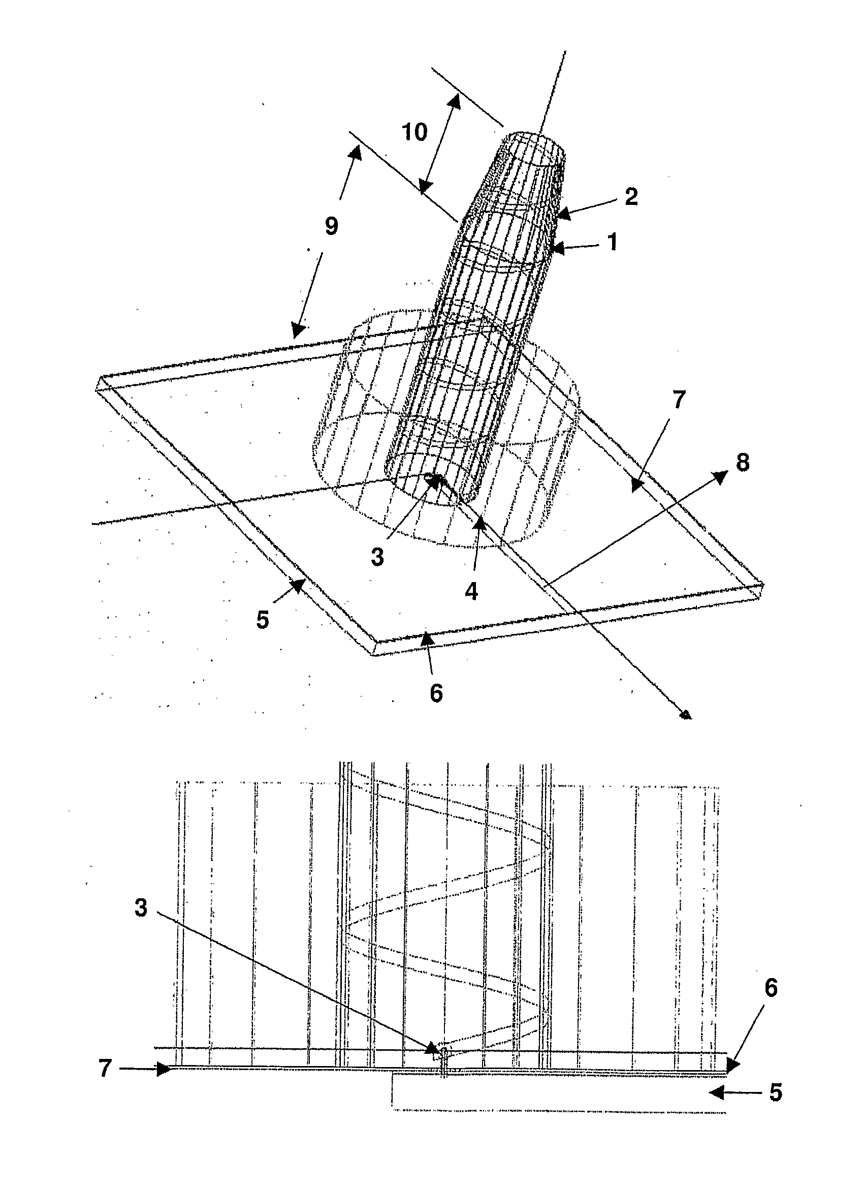
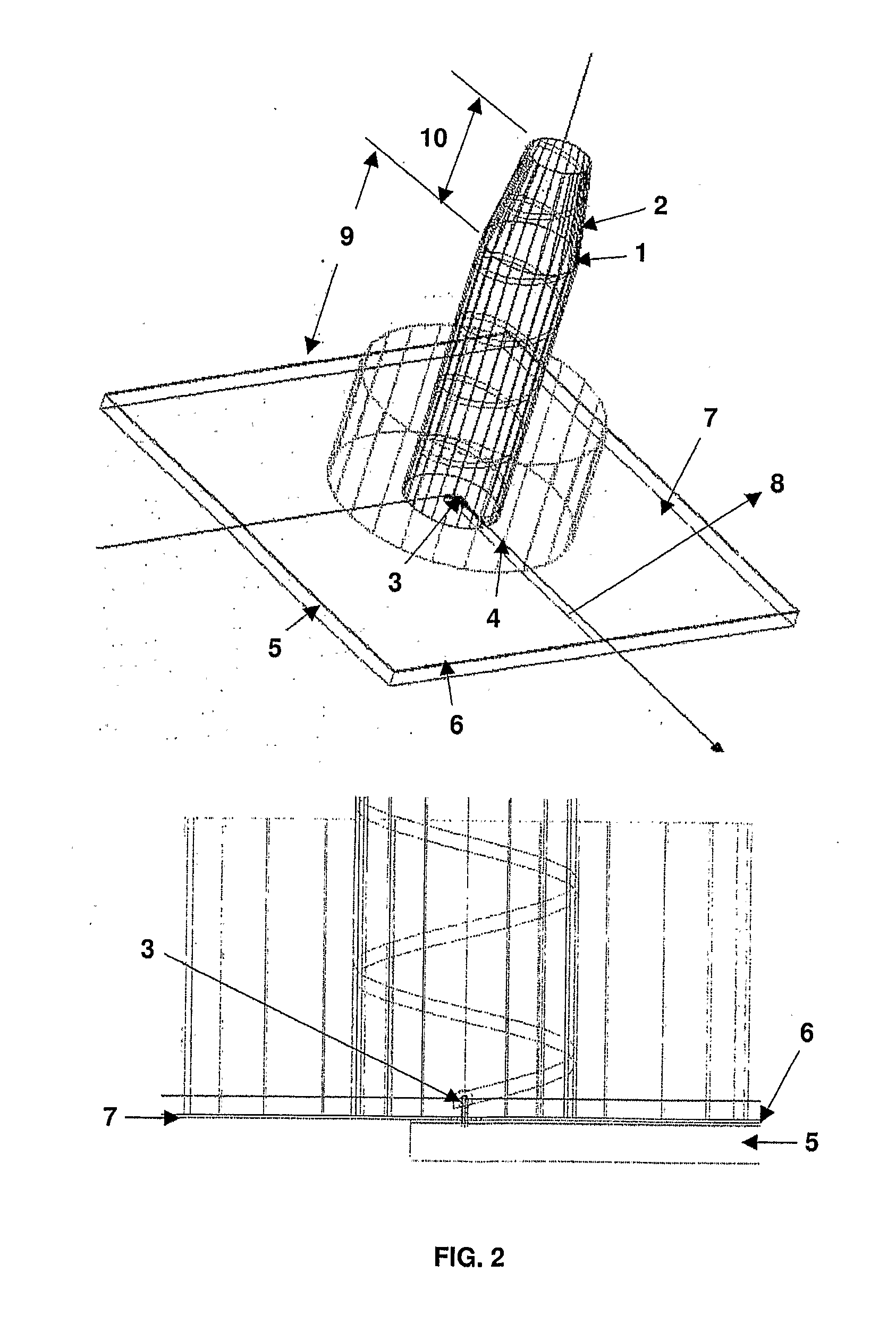
[0028]Referring to FIG. 2, a 3D-view of a printed quasi-tapered tape helical element is illustrated, in accordance with an exemplary embodiment of the present invention. The printed quasi-tapered tape helical element comprises a flat ultra thin helix conductor 1 that is printed on thin dielectric sheet. The printed helix conductor 1 is bonded to a hollow composite dielectric support 2. Since the flat ultra thin printed helix conductor 1 is lightweight as compared to the copper wire or a conducting hollow tube as a helix conductor, thus a quasi-tapered printed helical antenna is compact in geometry with very low on-axis and off-axis axial ratio along with required gain. Such quasi-tapered helix element exhibits shorter length than the uniform helix element for the specified RF performance.

[0029]In addition, a solid copper conductor 3 connects the tape helical conductor 1 to a microstrip line of a microstrip feed network circuit 8, where the copper conductor 3 also functions as impeda...


PUM


Abstract

A printed quasi-tapered tape helical element and printed helical array antenna arc disclosed. The helical element comprises a thin helix conductor having a uniform section associated with a tapered section. The helix conductor can be printed on a thin dielectric sheet and bonded to a hollow composite dielectric support. A solid copper conductor is configured to provide electrical connection between a feeding point of the helix conductor and a microstrip line of a microstrip feed network. The uniform and tapered helix turns are respectively wrapped around the uniform and tapered sections, which enables impedance matching, axial mode excitation, gain and radiation patterns, and damping out of standing waves generated in current distribution over the helix conductor. Conductive composite cups surrounding each helical element reduces mutual coupling in array environment. Thus, the helical element and the array antenna achieve low on-axis and off-axis axial ratio performance over the wideband for global coverage.

Description

CROSS-REFERENCE TO RELATED APPLICATIONS[0001]This application is a National Stage application of International Application No. PCT / IN2009 / 000517, filed on Sep. 22, 2009, which claims priority of Indian patent application number 1876 / CHE / 2009, filed on Aug. 6, 2009, both of which are incorporated herein by reference in their entireties.BACKGROUND OF THE INVENTION[0002]1. Field of the Invention[0003]The present invention relates to the fields of antennas for space applications. The present invention specifically relates to a printed quasi-tapered tape helical element and quasi-tapered helical array antenna.[0004]2. Description of the Prior Art[0005]Traditionally, helix antennas are realized with electrical conductors such as solid or hollow conductors, supported by an electrically insulating material. Sometimes, helix conductor is extended through balun to the coaxial connector as an electrical connection. The dielectric aims extending from the metallic support at the centre are used ...

Claims


Application Information

Patent Timeline
Patent Type & Authority Applications(United States)
IPC IPC(8): H01Q1/50H01Q1/36
CPCH01Q1/523H01Q21/067H01Q11/083
Inventor SHASHI, BHUSHAN SHARMARAJEEV, JYOTIHARJIVAN, SANANDIYASAGI, SRAVAN KUMARYOGESH, HARSHADRAI TRIVEDIBHARGAV, NALINKANT PANDYA
Owner INDIAN SPACE RES ORG OF ISRO
Why Eureka
Try Eureka