Clock Data Recovery System

Active Publication Date: 2012-07-26
TEXAS INSTR INC
View PDF7 Cites 10 Cited by
  • Summary
  • Abstract
  • Description
  • Claims
  • Application Information

AI Technical Summary

Problems solved by technology

Consequently, there remain unmet needs

Method used


Image

  • Clock Data Recovery System
  • Clock Data Recovery System
  • Clock Data Recovery System

Examples


Embodiment Construction

[0013]As used in the specification and the appended claim(s), the singular forms “a,”“an” and “the” include plural referents unless the context clearly dictates otherwise. Similarly, “optional” or “optionally” means that the subsequently described event or circumstance may or may not occur, and that the description includes instances where the event or circumstance occurs and instances where it does not.

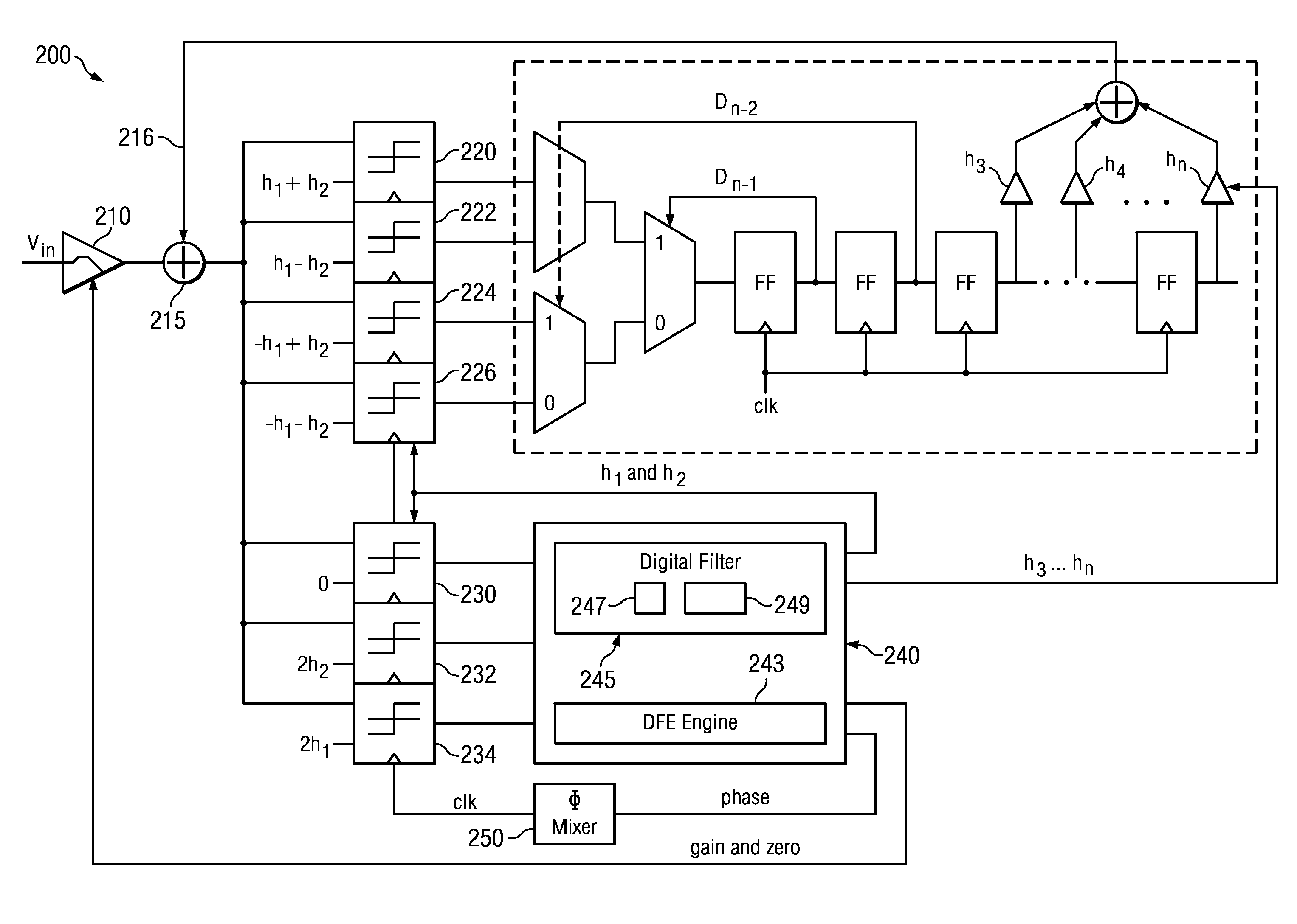
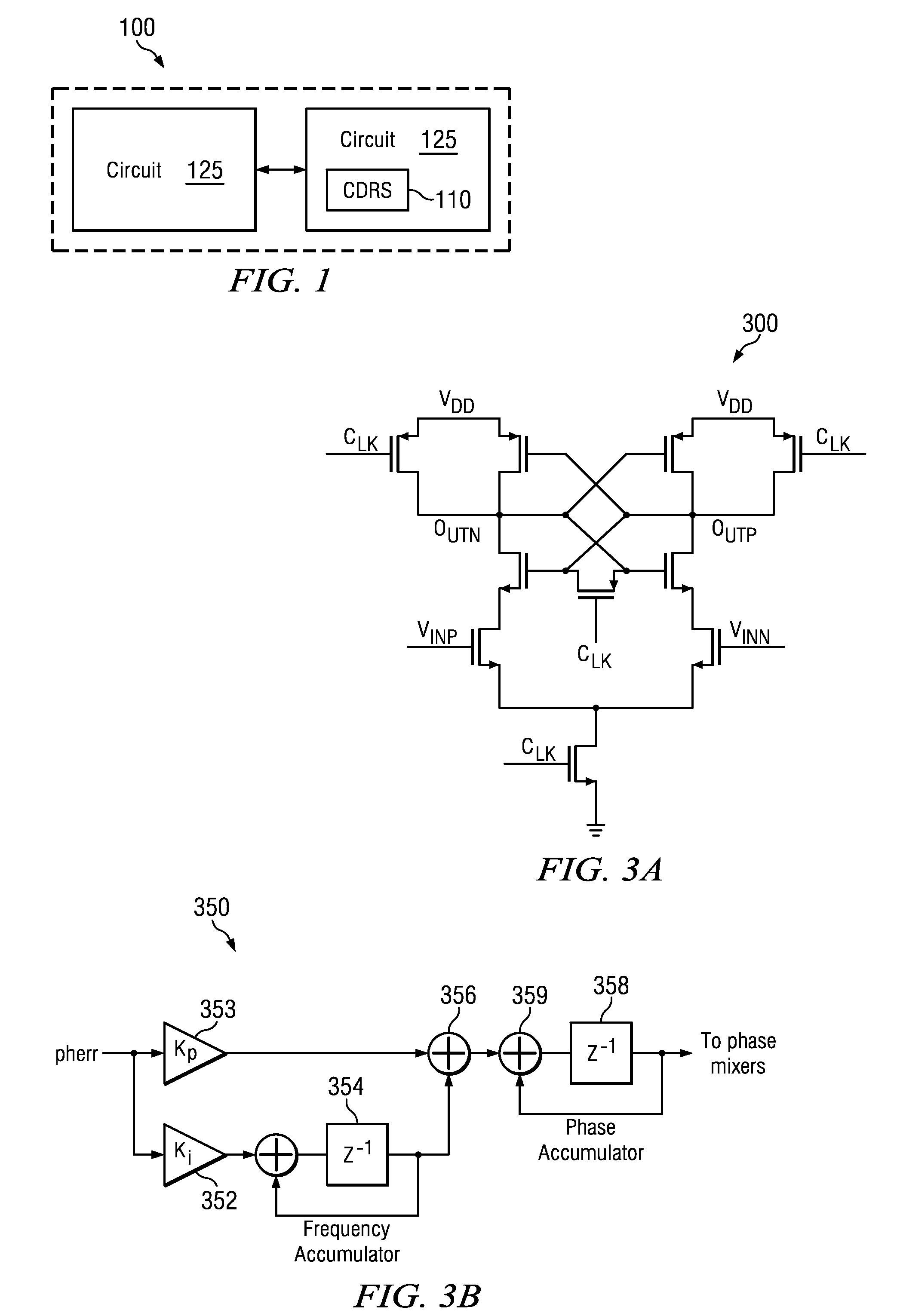
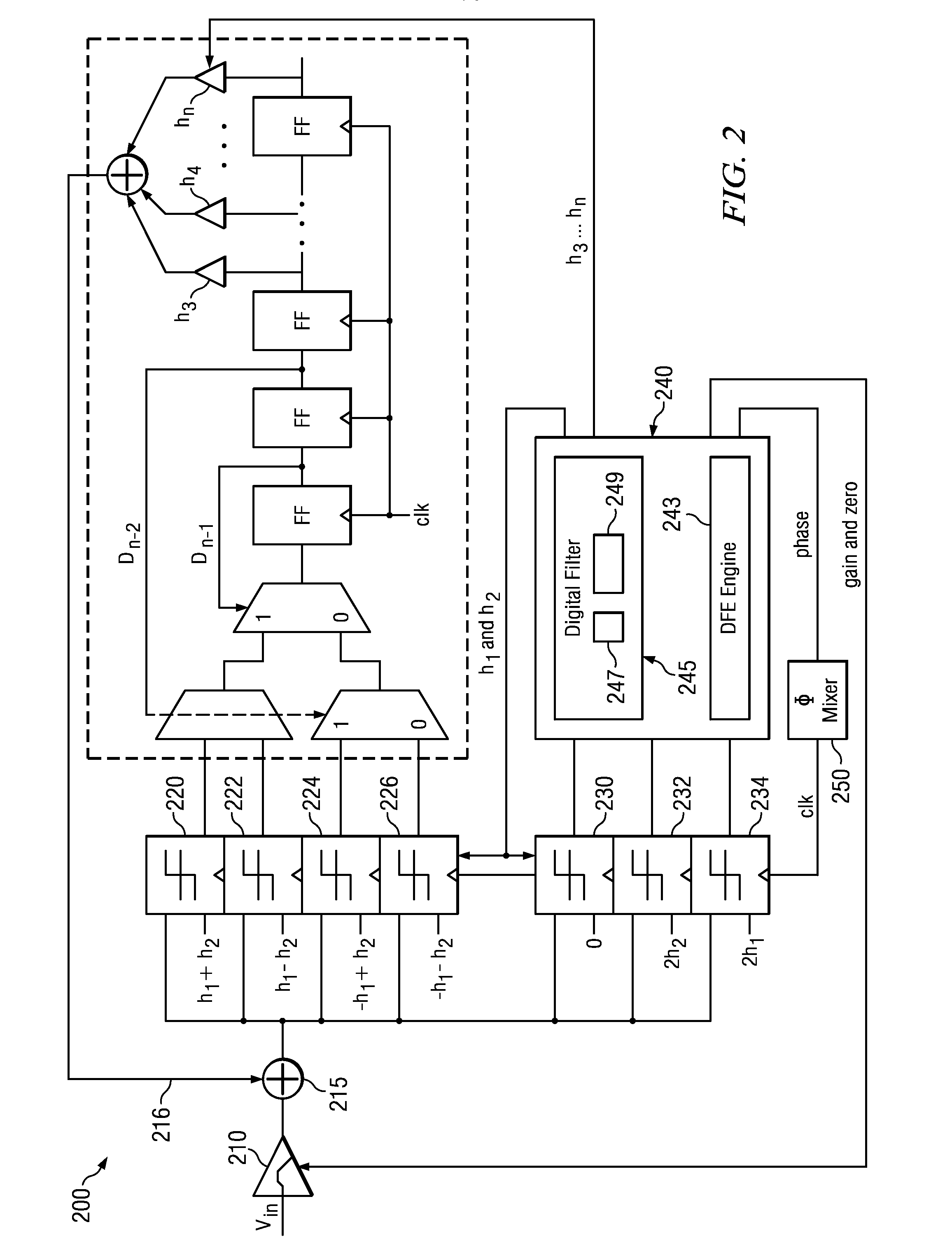
[0014]FIG. 1 is an illustrative environmental drawing 100 illustrating an innovative clock data recovery system (CDRS) 110. In this implementation, CDRS 110 may facilitate the exchange of data among circuits, such as circuit 120 and circuit 125. For example, the CDRS 110 may be in high speed serial links between chips used with computer servers, data switches, Internet services or the link. These serial links may have data transfer rates on the order of approximately 17 Gbps. At a high level, the CDRS 110 performs 2-tap partial response equalization with baud rate clock recovery. The...


PUM


Abstract

A clock data recovery system is described. It includes a high pass filter for transmitting a filtered data signal in response to receiving an input data signal; an adder for summing the filtered data signal with a feedback signal, wherein the adder produces a summed input signal; a plurality of clocked data comparators for receiving the summed input signal, wherein the clocked data comparators determine an input data bit value; a plurality of clocked error comparators for receiving an error signal associated with clock recovery and DFE tap adaption; an equalization and adaptation logic for selecting an error sample such that a phase associated with the error sample is locked at h0=h1+h2; and a phase mixer for transmitting a delay in response to receiving the phase and the delay is transmitted to the clocked-data comparators and the clocked-error comparators.

Description

CROSS REFERENCE TO RELATED APPLICATION(S)[0001]The present application claims priority to jointly owned U.S. Provisional Application corresponding to application No. 61 / 436,440 entitled “Clock Data Recovery System.” This provisional application was filed on Jan. 26, 2011.DESCRIPTION OF RELATED ART[0002]With the evolution of electronic devices, there is a continual demand for enhanced speed, capacity and efficiency in various areas including electronics, communications, and machinery. This is particularly true with the growing focus on efficiency in data exchanges. Consequently, there remain unmet needs relating to efficient data exchanges.BRIEF DESCRIPTION OF THE DRAWINGS[0003]The clock data recovery system may be better understood with reference to the following figures. The components within the figures are not necessarily to scale, emphasis instead being placed upon clearly illustrating the principles of the invention. Moreover, in the figures, like reference numerals designate c...

Claims


Application Information

Patent Timeline
IPC IPC(8): G06F11/07
CPCH03K3/356173H04L25/03057H04L7/0087H04L7/0054
Inventor LEE, HAE-CHANGJOY, ANDREW KEITHFELDMAN, ARNOLD ROBERT
Owner TEXAS INSTR INC
Why Eureka
Try Eureka