

Engine System
a technology of engine and wastegate, which is applied in the direction of machines/engines, mechanical equipment, cylinders, etc., can solve the problems of large size of turbocharger and wastegate assembly, and inability to heat other components, so as to prevent over-speeding of turbocharger, reduce emissions, and improve power outpu
- Summary
- Abstract
- Description
- Claims
- Application Information
AI Technical Summary
Benefits of technology
Problems solved by technology
Method used
Image

Examples
first embodiment
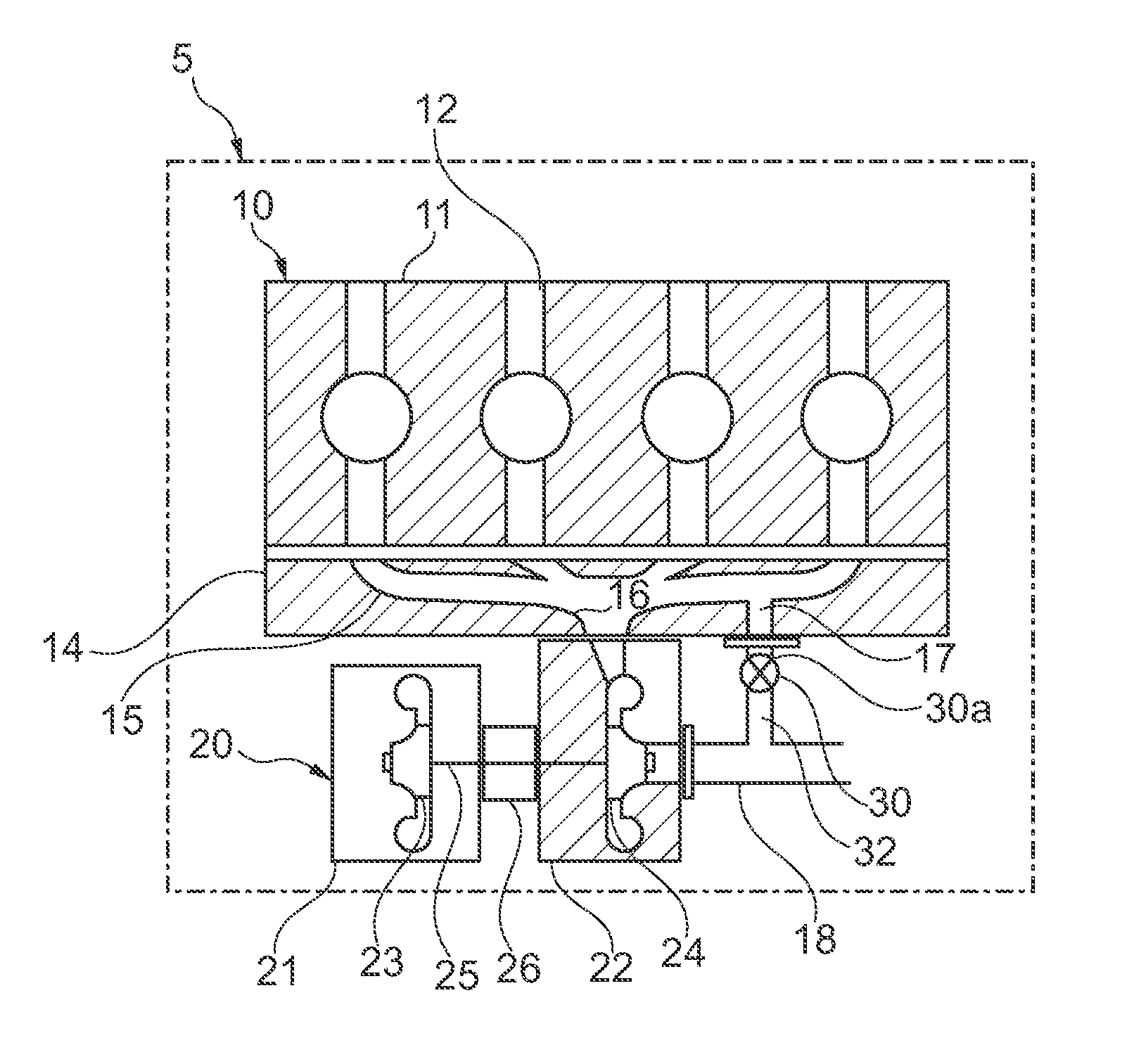
[0049]In a cooling circuit shown in FIG. 3, coolant is circulated by a coolant pump 2 from a radiator 1 via a top hose TL and a supply hose SL to the engine 10 and in this case to the cylinder head 11 (it will be appreciated that the supply hose SL could alternatively be connected to a cylinder block (not shown) of the engine 10). The coolant from the supply hose SL flows through the cylinder block, the cylinder head 11 and the liquid cooled manifold 14 and directly from the liquid cooled manifold 14 into the turbocharger housing 22. The coolant then flows through the cooling passages in the turbine housing 22 and out of the liquid cooled turbine housing 22 via a return hose RL to the radiator 1. (It will be appreciated that there may be a separate return from a cylinder block of the engine 10 via the return hose RL). As is usual in such a cooling circuit a coolant bypass line BL controlled by a combine bypass and thermostat valve 3 connects the return hose RL and the top hose TL so...
second embodiment
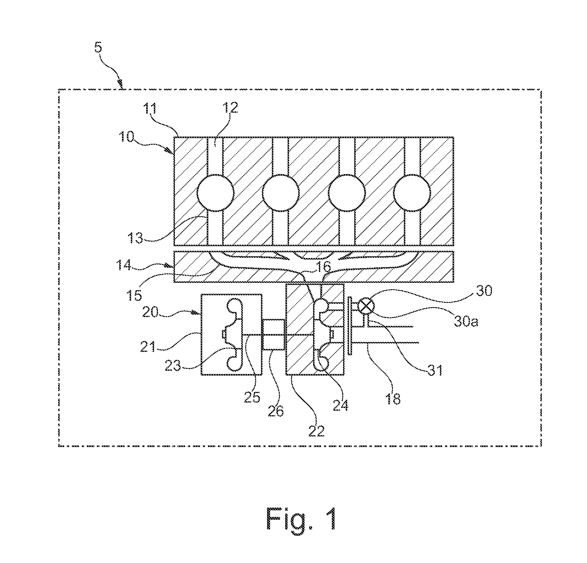
[0050]In a cooling circuit shown in FIG. 4, coolant is circulated by a coolant pump 2 from a radiator 1 via a top hose TL and a supply hose SL to the engine 10 and in this case to the cylinder head 11 (it will be appreciated that the supply hose could alternatively be connected to a cylinder block (not shown) of the engine 10). The coolant from the supply hose SL flows through the cylinder block, cylinder head 11 and liquid cooled manifold 14 and from the liquid cooled manifold 14 into a return hose RL to the radiator 1. (It will be appreciated that there may be a separate return from the cylinder block of the engine 10 via the return hose RL).
[0051]As is usual in such a cooling circuit a coolant bypass line BL controlled by a combine bypass and thermostat valve 3 connects the return hose RL and the top hose TL so as to provide a coolant flow path that is arranged in parallel to the radiator 1.
[0052]The liquid cooled turbine housing 22 in this case is cooled by a secondary cooling c...
third embodiment
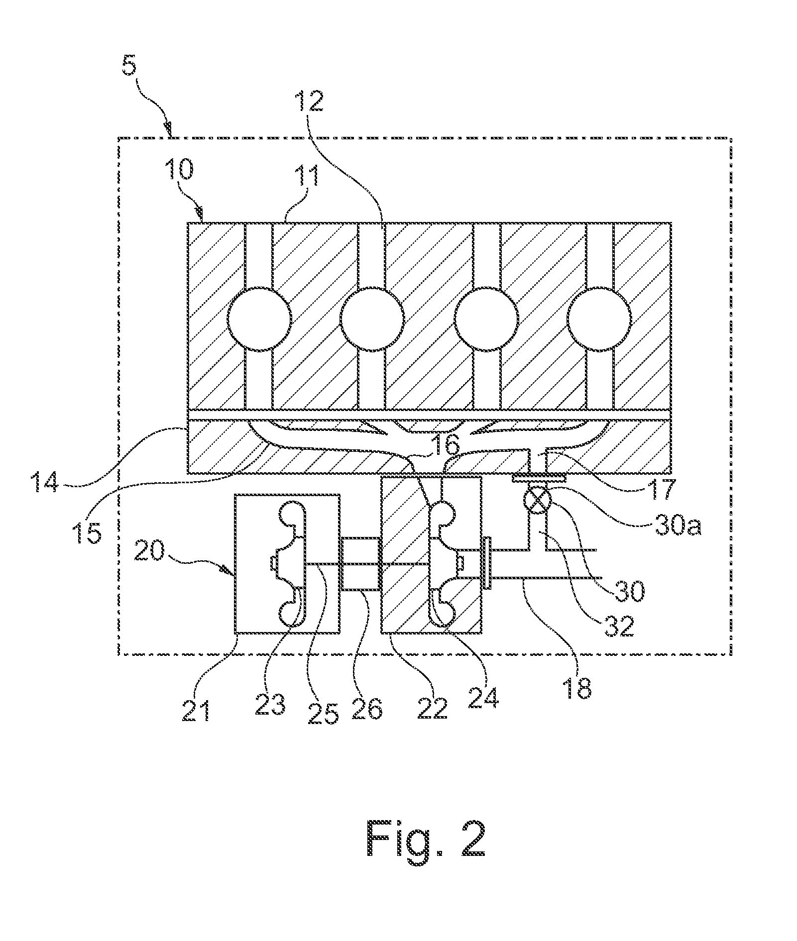
[0053]In a cooling circuit shown in FIG. 5, coolant is circulated by a coolant pump 2 from a radiator 1 via a top hose TL and a supply hose SL to the engine 10 and in this case to the cylinder head 11 (it will be appreciated that the supply hose could alternatively be connected to a cylinder block (not shown) of the engine 10). The coolant from the supply hose SL flows through the cylinder block, cylinder head 11 and liquid cooled manifold 14 and from the liquid cooled manifold 14 into a return hose RL to the radiator 1. (It will be appreciated that there may be a separate return from a cylinder block of the engine 10 via the return hose RL)
[0054]As is usual in such a cooling circuit a coolant bypass line BL controlled by a combine bypass and thermostat valve 3 connects the return hose RL and the top hose TL so as to provide a coolant flow path that is arranged in parallel to the radiator 1.
[0055]The liquid cooled turbine housing 22 in this case is cooled by a supply of coolant draw...
PUM
 Abstract
Description
Claims
Application Information