Aircraft fuel system

Inactive Publication Date: 2012-08-02
AIRBUS OPERATIONS LTD
View PDF23 Cites 40 Cited by
  • Summary
  • Abstract
  • Description
  • Claims
  • Application Information

AI Technical Summary

Benefits of technology

[0025]A problem introduced by this unequal venting capacity is that the oxygen concentration may increase to an unacceptable level in the first cell. This unequal venting capacity is counteracted in two ways: firstly, by providing the ability for gas to flow across the baffle(s) between the cells in order to reduce any difference in oxygen concentration between them; and secondly, by focussing the oxygen-deplete

Problems solved by technology

This system is good during ideal descent cases but for descents that include, for example, loiter or go-around, i.e. where the aircraft levels out in altitude or ascends, the NEA within the surge tank and vent line will expel overboard, which does not reduce the burden o

Method used


Image

  • Aircraft fuel system
  • Aircraft fuel system
  • Aircraft fuel system

Examples


Example

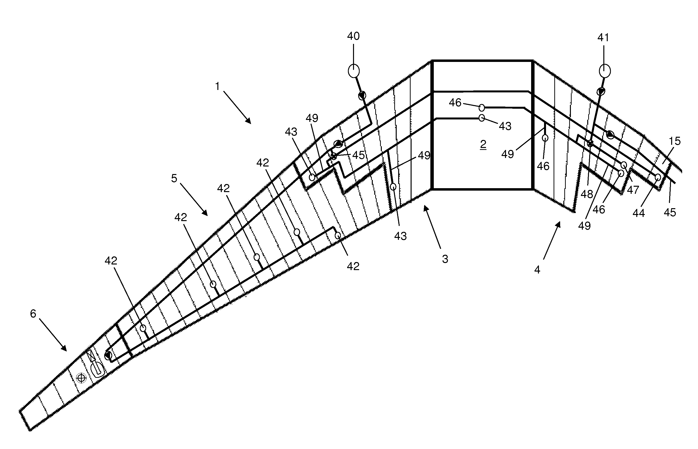
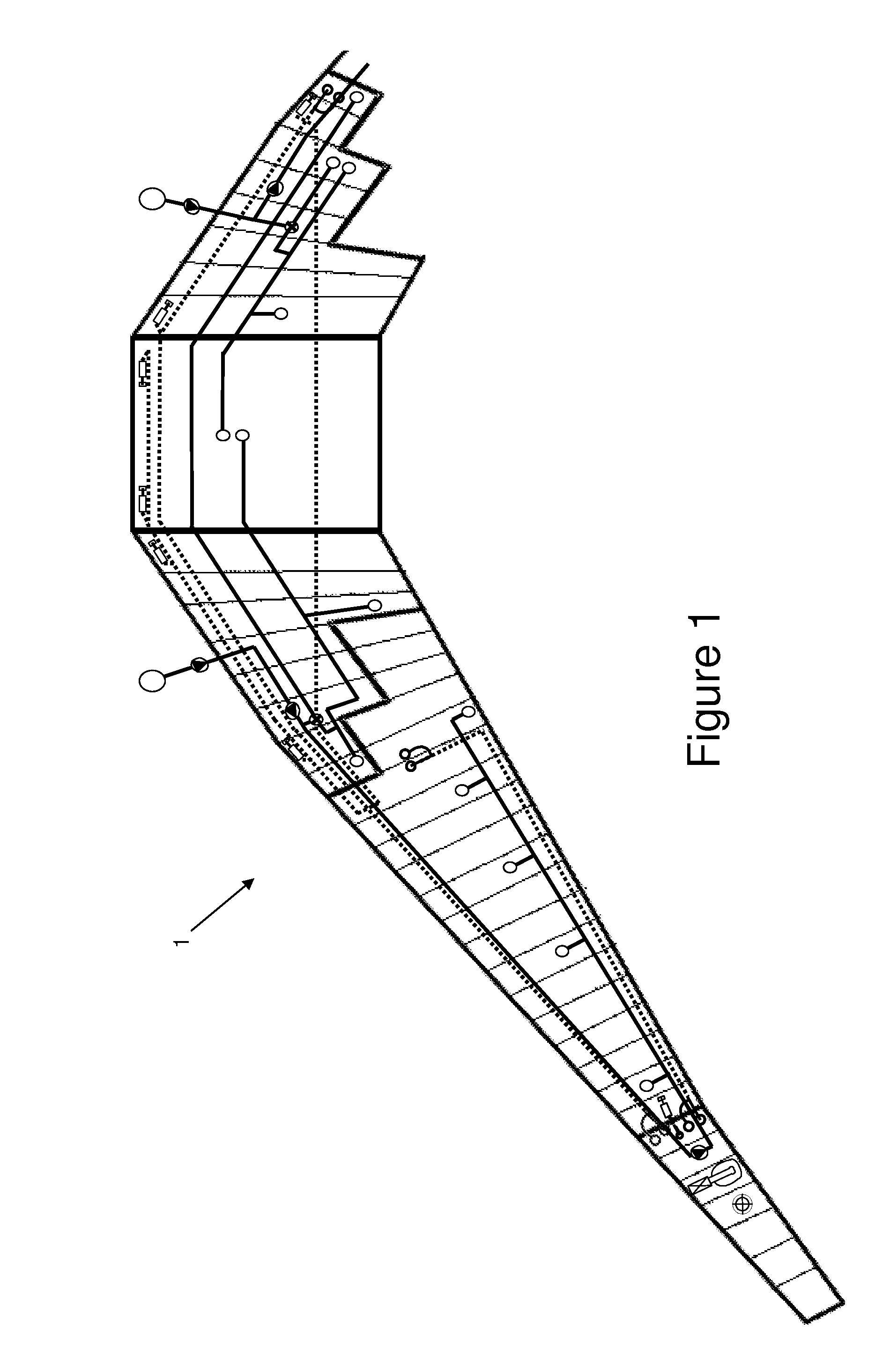
[0037]FIG. 1 is a plan view of part of an aircraft fuel tank system 1. The various elements of the system are shown together in FIG. 1, and separately in FIGS. 2-4.

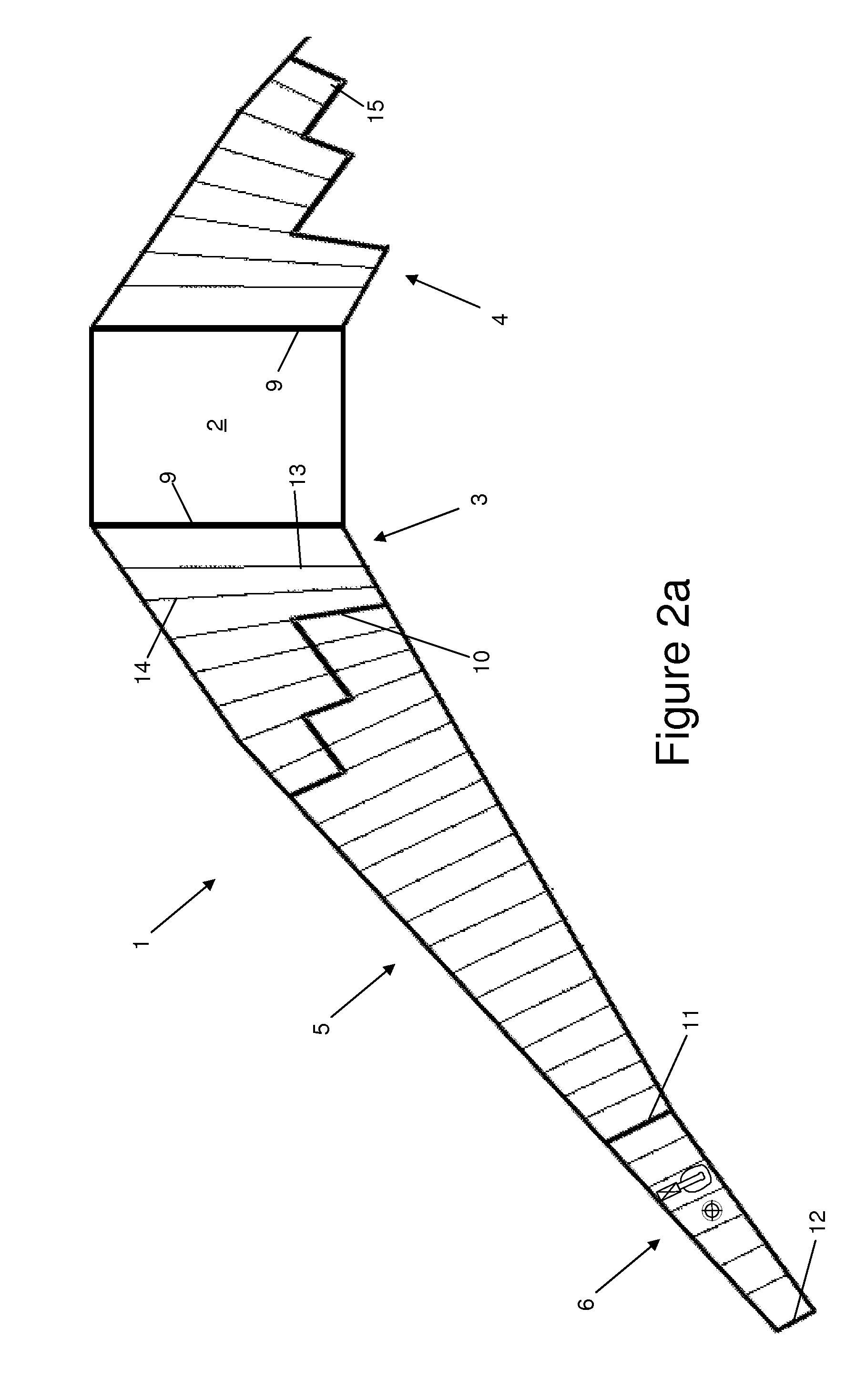
[0038]The fuel tank system 1 comprises a set of fuel tanks, a venting system and an inerting system. FIG. 2a shows the fuel tank system 1 with the inerting system and venting system omitted. The system 1 comprises a centre wing tank with a fuel tank bay 2 (located under the aircraft fuselage) and port and starboard inner wing fuel tank compartments 3,4; port and starboard outer wing fuel tanks (only the port outer wing fuel tank 5 being shown); and port and starboard surge tanks (only the port surge tank 6 being shown). The centre bay 2 is bounded by a pair of ribs 9; the inner wing compartment 3 is bounded by rib 9 and a staggered wall 10 (shown in a thick line); the outer wing tank 5 is bounded by wall 10 and a rib 11; and the surge tank is bounded by rib 11 and an outermost rib 12. The tanks are bounded fore and aft by...


PUM


Abstract

An aircraft fuel system has a fuel tank with first and second cells separated by one or more baffles. A venting system reduces pressure difference between the interior and exterior of the fuel tank, and an inerting system supplies oxygen-depleted gas to the fuel tank. The baffles permit the flow of fluid between the cells. The venting system has one or more vent nozzles within the fuel tank and in fluid communication with one or more vent ports. The inerting system has one or more inerting nozzles for injecting oxygen-depleted gas into the first and second cells. A control device varies the ratio between the total flow rates of the oxygen-depleted gas into the first and second cells.

Description

FIELD OF THE INVENTION[0001]The present invention relates to an aircraft fuel system with a fuel tank, a venting system for reducing pressure difference between the interior and exterior of the fuel tank, and an inerting system for supplying oxygen-depleted gas to the fuel tank.BACKGROUND OF THE INVENTION[0002]U.S. Pat. No. 7,204,868 describes a conventional aircraft fuel system with a fuel tank, a venting system for reducing pressure difference between the interior and exterior of the fuel tank, and an inerting system for supplying oxygen-depleted gas to the fuel tank. During descent, oxygen-rich air flows into the tank via the venting system and nitrogen-enriched air (NEA) from an air separation module (ASM) is injected into the venting system to pre-inert the vent in-flux. During a fast descent, NEA air is also injected into the tank via a separate set of inerting nozzles.[0003]This system is good during ideal descent cases but for descents that include, for example, loiter or go...

Claims


Application Information

Patent Timeline
IPC IPC(8): B64D37/08B64D37/32
CPCB64D37/08Y02T50/44B64D37/32Y02T50/40
Inventor ROSCOE, PAULLEHUUNHO, EMMANUEL
Owner AIRBUS OPERATIONS LTD
Why Eureka
Try Eureka