Method of Enhancing 3D Image Information Density

a 3d image and information density technology, applied in the field of processing 3d images, can solve the problems of reducing the spatial reliability of reconstructed high-resolution neural network images, limiting mechanical or physical properties, and reducing the resolution of the reconstructed high-resolution image, so as to achieve the effect of enhancing the 3d image information density and poor resolution

Active Publication Date: 2012-08-02
NATIONAL TSING HUA UNIVERSITY
View PDF7 Cites 25 Cited by
  • Summary
  • Abstract
  • Description
  • Claims
  • Application Information

AI Technical Summary

Benefits of technology

[0004]It is therefore an object of the invention to provide a method of enhancing 3D image information density through integrating multi-angle images to overcome the issue of poor resolution in Z-direction in confocal microscopy due to the limitation of mechanical or physical properties.

Problems solved by technology

However, the 3D image has a lower resolution in the Z-axis direction (e.g., about 1.2 μm / slice) than in the X-axis and Y-axis directions (about 0.15 μm / pixel) under the limitation of mechanical or physical properties.
And the lower resolution in the Z-axis direction hampers the spatial reliability of the reconstructed high resolution neural network images, especially when comparison of two different samples is necessary.

Method used


Image

  • Method of Enhancing 3D Image Information Density
  • Method of Enhancing 3D Image Information Density
  • Method of Enhancing 3D Image Information Density

Examples


Embodiment Construction

[0030]The invention hereinafter will be described in detail with preferred embodiments of the invention and accompanying illustrations. Nevertheless, it should be recognized that the preferred embodiments of the invention are not provided to limit the invention but to illustrate it. The present invention can be practiced not only in the preferred embodiments herein mentioned, but also in a wide range of other embodiments besides those explicitly described. Furthermore, the scope of the present invention is expressly not limited to any particular embodiments except what is specified in the appended Claims.

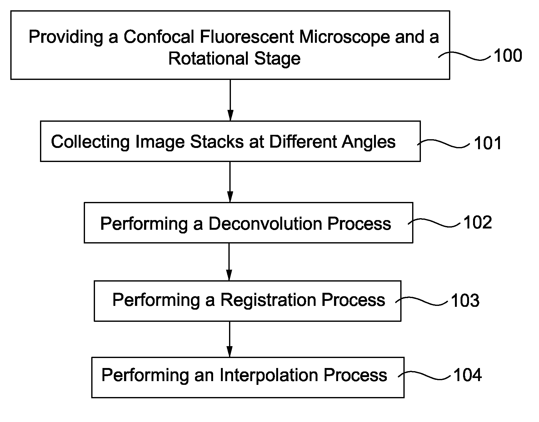
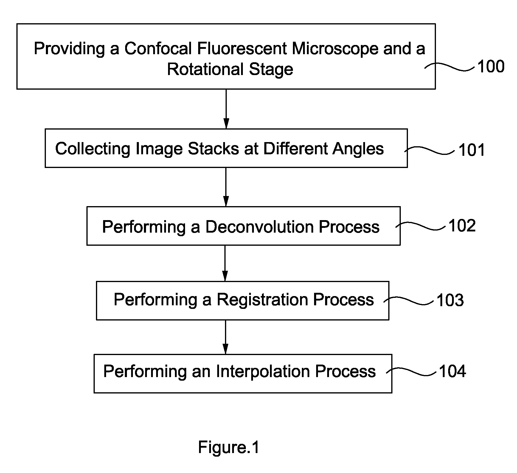
[0031]The present invention discloses a method of enhancing 3D image information density. FIG. 1 is a flowchart showing a method of enhancing 3D image information density according to an embodiment of the present invention.

[0032]With reference to FIG. 1, the method of enhancing 3D image information density of the present invention includes providing a confocal fluorescent microscope...


PUM


Abstract

A method of enhancing 3D image information density, comprising providing a confocal fluorescent microscope and a rotational stage. 3D image samples at different angles are collected. A deconvolution process of the 3D image samples by a processing unit is performed. A registration process of the deconvoluted 3D image samples by the processing unit is performed. An interpolation process of the registered 3D image samples by the processing unit is performed to output a 3D image in high resolution.

Description

TECHNICAL FIELD[0001]The invention relates in general to a method of processing 3D image, and more particularly to a method of enhancing 3D image information density.BACKGROUND OF THE INVENTION RELATED ART[0002]Confocal laser scanning microscopy (CLSM) is a valuable tool for obtaining high resolution images and 3D reconstructions by using a spatial pinhole to eliminate out-of-focus light or flare. This technology permits one to obtain images of various Z-axis planes (Z-stacks) of the sample. The detected light from an illuminated volume element within the specimen represents one pixel in the resulting image. As the laser scans over the plane of interest, where the beam is scanned across the sample in the horizontal plane by using one or more (servo-controlled) oscillating mirrors, the whole image is obtained pixel by pixel and line by line. Information can be collected from different focal planes by raising or lowering the microscope stage. Then the computer can calculate and genera...

Claims


Application Information

Patent Timeline
Patent Type & Authority Applications(United States)
IPC IPC(8): H04N13/02
CPCG02B21/008G06T3/4007G02B21/367G02B21/16
Inventor CHIANG, ANN-SHYNCHANG, HSIU-MINGCHEN, YUNG-CHANGCHEN, KUAN-YU
Owner NATIONAL TSING HUA UNIVERSITY
Why Eureka
Try Eureka