Method for electronically determining the shooting position on a shooting target

a technology of electronic determination and shooting position, applied in the direction of optical detection, weapons, instruments, etc., can solve the problems of comparatively high buying cost and corresponding running cost, and achieve the effect of small complexity

Inactive Publication Date: 2012-08-02
SIUS
View PDF4 Cites 23 Cited by
  • Summary
  • Abstract
  • Description
  • Claims
  • Application Information

AI Technical Summary

Benefits of technology

[0043]Thereby it is advantageous that the shooting target is formed in such a way that, seen in the intended shooting direction, a circular area of maximum diameter, which can be defined within the optical screen, thus within the area inside which the pass-through position of a projectile through the optical screen can be determined by the signals provided by the photo-electric light receivers, is congruent with the target opening or extends to a minimum extent beyond the limits of the target opening. By this, the shooting target can be designed in a particularly economical way because the optical shooting position determination only has to be dimensioned for the central area and has an accordingly smaller complexity as compared to purely optical measurement systems. In the last mentioned case that the circular area of maximum diameter, seen in the intended shooting direction, extends to a minimum extent beyond the limits of the target opening, the advantage results that a possibly imprecise acoustic shooting position determination in the edge area of the target opening can be replaced by or complemented with the optical shooting position determination.

Problems solved by technology

They are, however, comparatively expensive to buy.
The acoustic systems are much more economical to buy than the optical systems, however, they require in any case a screen made of canvas-like or plate-like material forming the target surface, which is perforated during the passage and which has to be renewed, this being coupled with corresponding running costs.

Method used


Image

  • Method for electronically determining the shooting position on a shooting target
  • Method for electronically determining the shooting position on a shooting target
  • Method for electronically determining the shooting position on a shooting target

Examples


Embodiment Construction

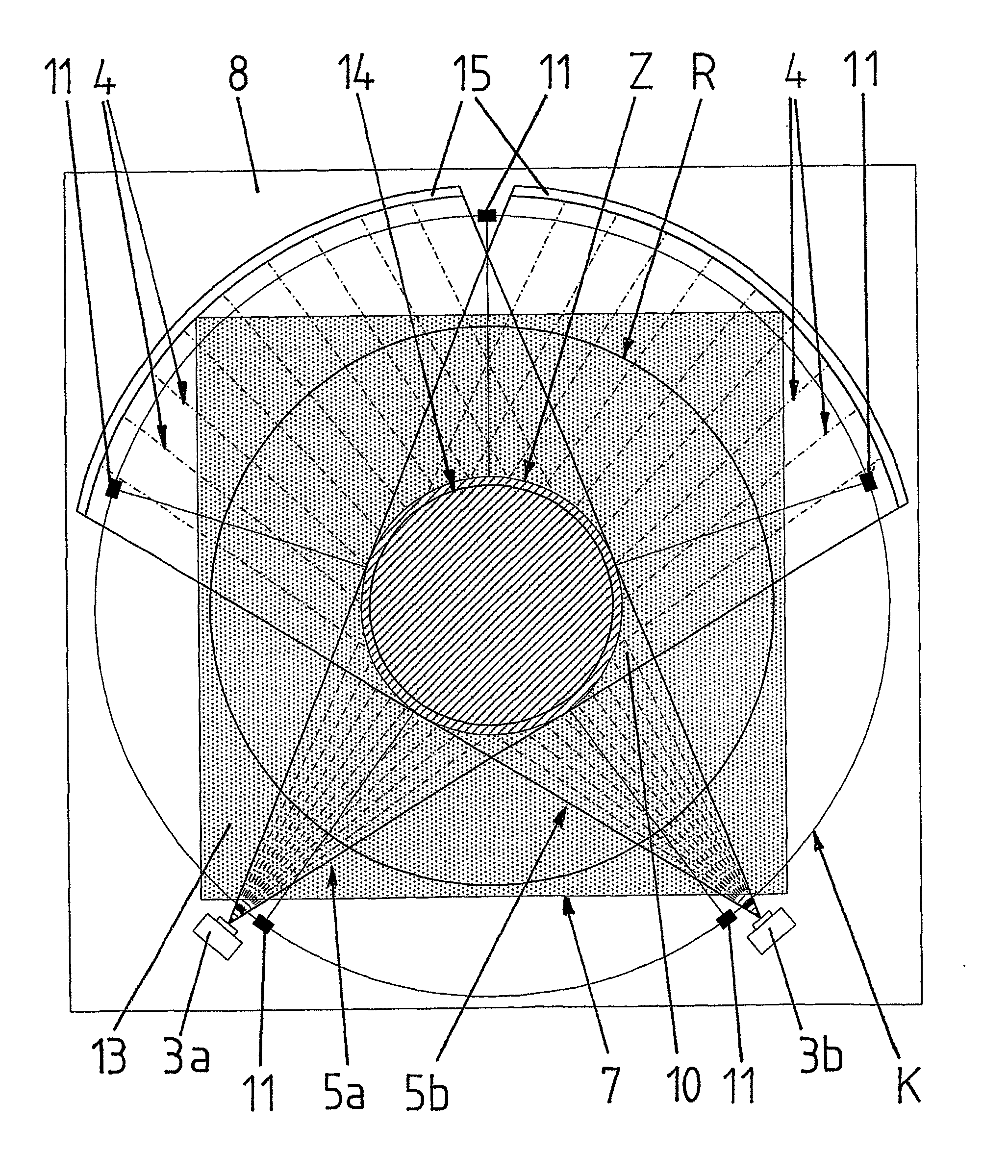
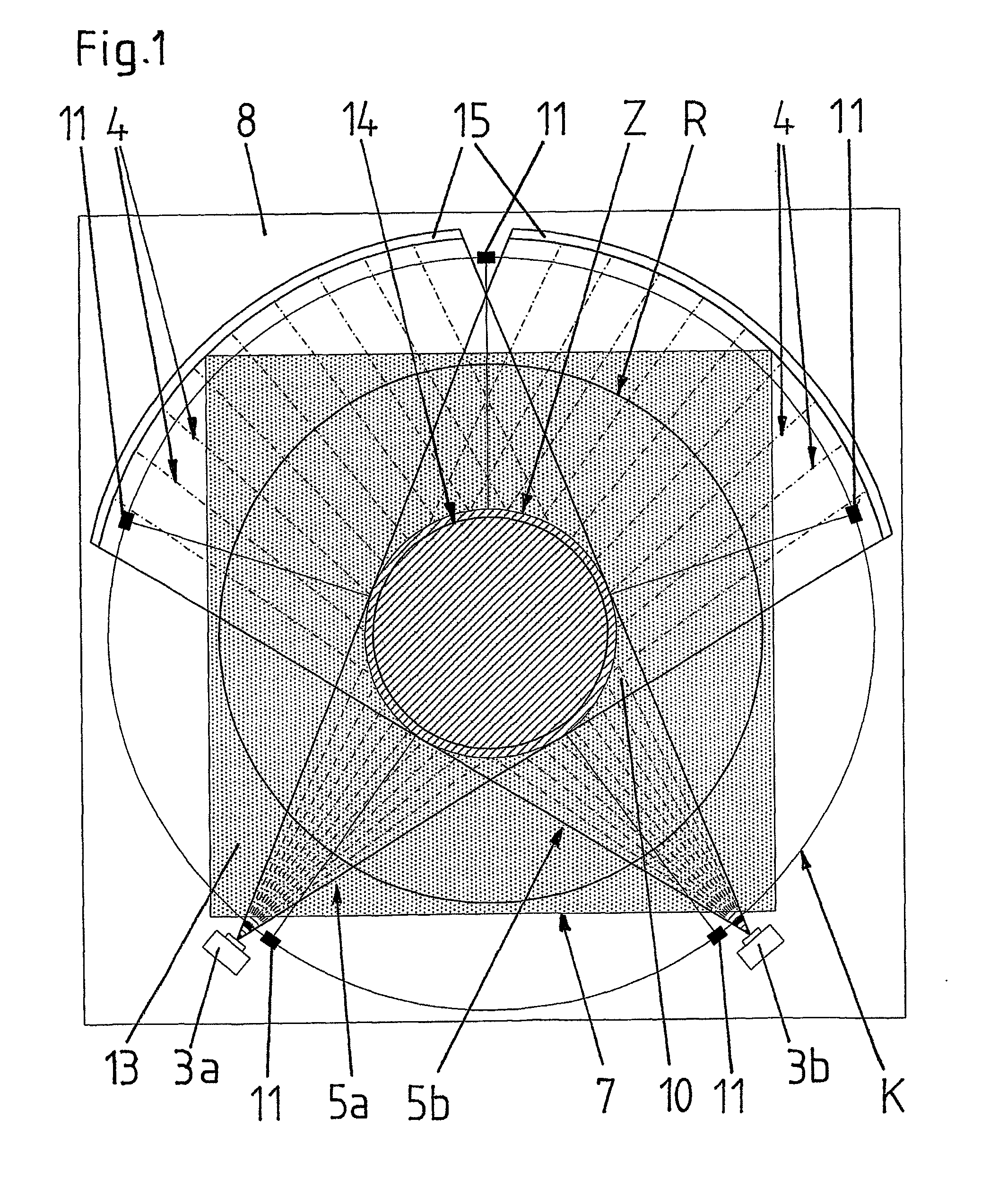
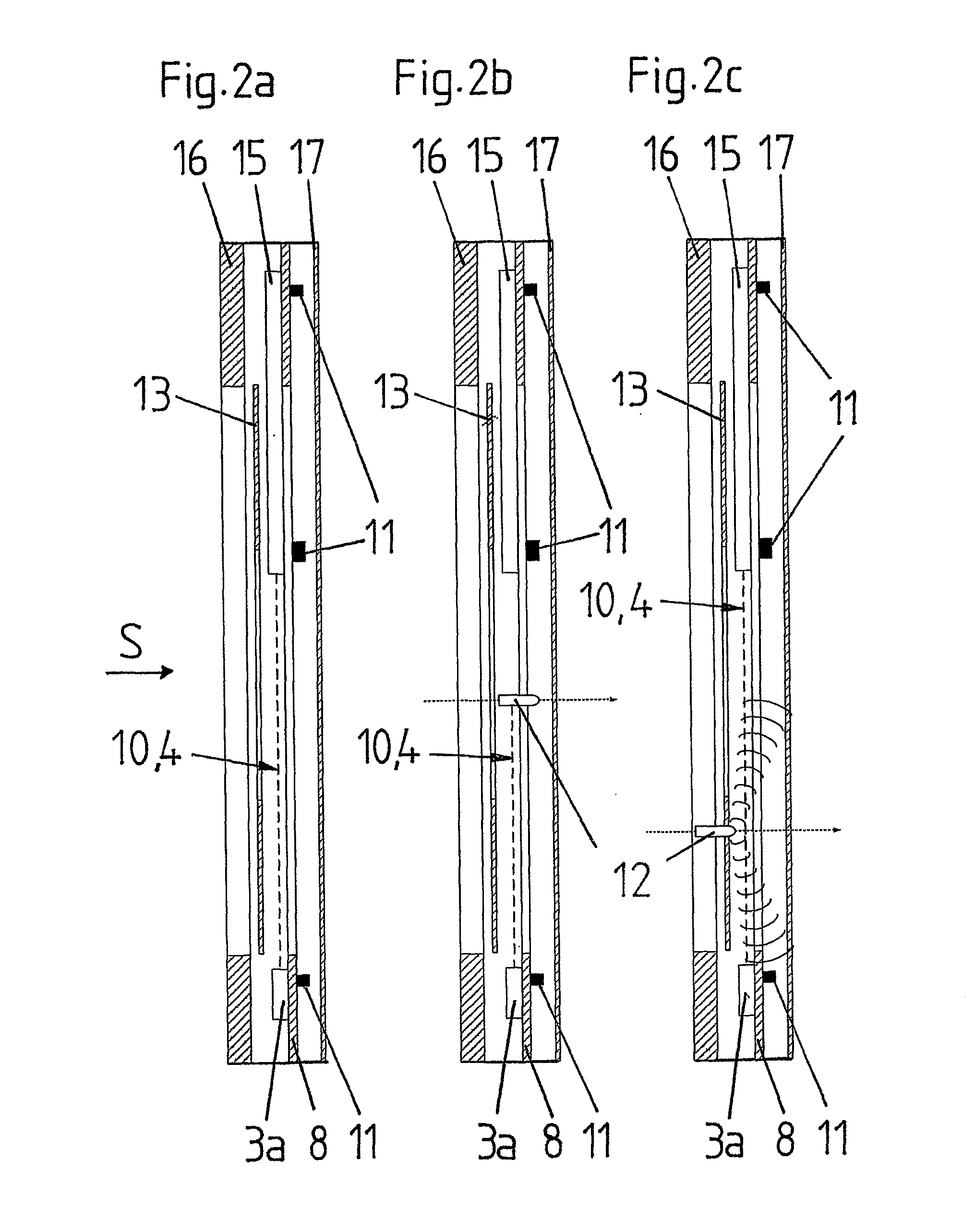
[0051]The basic concept of the invention results from FIGS. 1 and 2a to 2b, which show in a very schematic way a top view on a shooting target according to the invention (FIG. 1) as well as vertical sections through the shooting target in different situations (FIGS. 2a to 2c).

[0052]As can be seen when looking at these figures in combination, the shooting target comprises a circuit board 8 with a central section 7 which, seen in the intended shooting direction S, has on its front side rows 15 composed of a plurality of individual photo-electric light receivers and light sources 3a, 3b for sending light which can be detected by the light receivers. The rows 15 of light receivers and the light sources 3a, 3b are arranged relatively to each other in such a way that an optical path 4 (shown by the dashed lines) is formed between each one of the light receivers of the rows 15 and one of the light sources 3a, 3b, via which the respective light receiver can receive light from one of the lig...


PUM


Abstract

The invention relates to a method for electronically determining the shooting position on a shooting target. Said shooting position is determined in a first impact area (Z) on the shooting target exclusively in an opto-electronic manner and in a second impact area on the shooting target exclusively in an acousto-electronic manner.
Said method enables the shooting position to be determined by means of relatively economical electronic systems and with only low running costs for user material, in which the shooting position is determined by means of an optical measurement system only in the relatively small central impact area (Z), which normally has a high impact frequency and which requires high precision for determining the shooting position, whereas the shooting position in the relatively large edge area surrounding said central area is determined by means of an economical acoustic system.

Description

TECHNICAL FIELD[0001]The present invention is related to a method for electronically determining the shooting position on a shooting target, an arrangement for electronically determining the shooting position on a shooting target according to the method as well as a shooting target, particularly a shooting disc, with the arrangement for carrying out the method according to the preambles of the independent claims.PRIOR ART[0002]Shooting targets with electronic shooting position determination are widespread as “electronic shooting targets” for training purposes as well as for shooting contests. The company Sius AG, Effretikon, Switzerland is the worldwide market leader for such installations, having been active in this field for decades.[0003]The presently known systems can be divided in acoustic and optical or photo-electric systems, respectively.[0004]In case of the acoustic systems, the acoustic wave generated when the projectile passes through the object forming the target surface...

Claims


Application Information

Patent Timeline
Patent Type & Authority Applications(United States)
IPC IPC(8): G01B11/14G01B5/14
CPCG01V8/20F41J5/02
Inventor WALTI-HERTER, HANSRUEDI
Owner SIUS
Why Eureka
Try Eureka