Chamber With Low Turbulence Argon Purging System

a chamber and chamber technology, applied in the direction of manufacturing tools, soldering devices, auxilary welding devices, etc., can solve the problems of large amount of idle time, time, and large amount of argon, so as to reduce time and gas, reduce the amount, and reduce the effect of mixing

Active Publication Date: 2012-08-09
PCC STRUCTURALS
View PDF17 Cites 3 Cited by
  • Summary
  • Abstract
  • Description
  • Claims
  • Application Information

AI Technical Summary

Benefits of technology

[0009]The present invention solves the problems heretofore encountered in purging-enclosed chambers by providing a system which greatly reduces the time and gas required to purge atmospheric air from the chamber and replace it with another gas, such as argon. The present invention accomplishes this desired result by introducing the replacement / purge gas into the enclosed chamber using a low turbulence, high flow purge system that produces a laminar flow front which displaces the atmospheric air in the chamber with very little mixing of the air and replacement / purge gas, such as argon. In a non-turbulent flow state, the argon remains below the atmospheric air in the chamber due to the higher density of argon relative to air and pushes the air from the chamber through exhaust means at the top of the chamber. The invention also provides a significant savings in the amount of inert gas, such as argon, required to displace the air in the chamber compared with current purging systems / methods. Briefly stated, the system of the present invention includes an enclosed chamber, a perforated plate having a plurality of through holes positioned within the chamber, a purge support plate positioned in a spaced relationship beneath the perforated plate and manifold means communicating with a plurality of spaced-apart diffusers mounted on the purge support plate. An inert gas source, such as argon, communicates with the manifold means. The inert gas passes through the diffusers and enters the space between the purge support plate and the perforated plate to subsequently pass through the spaced-apart holes and enter the chamber in a laminar flow front to purge the atmospheric air from the chamber. The chamber includes controlled vent means to permit the egress of the purged air and inert gas therefrom.

Problems solved by technology

In the manufacture / repair of complex investment cast shapes for aerospace, medical and land based systems markets, it is oftentimes necessary to perform a welding operation.
This process wastes large quantities of argon and time (decreases throughput and creates a large amount of idle time).

Method used


Image

  • Chamber With Low Turbulence Argon Purging System
  • Chamber With Low Turbulence Argon Purging System
  • Chamber With Low Turbulence Argon Purging System

Examples


Embodiment Construction

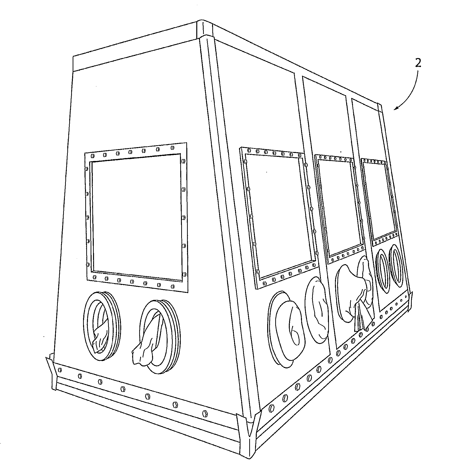
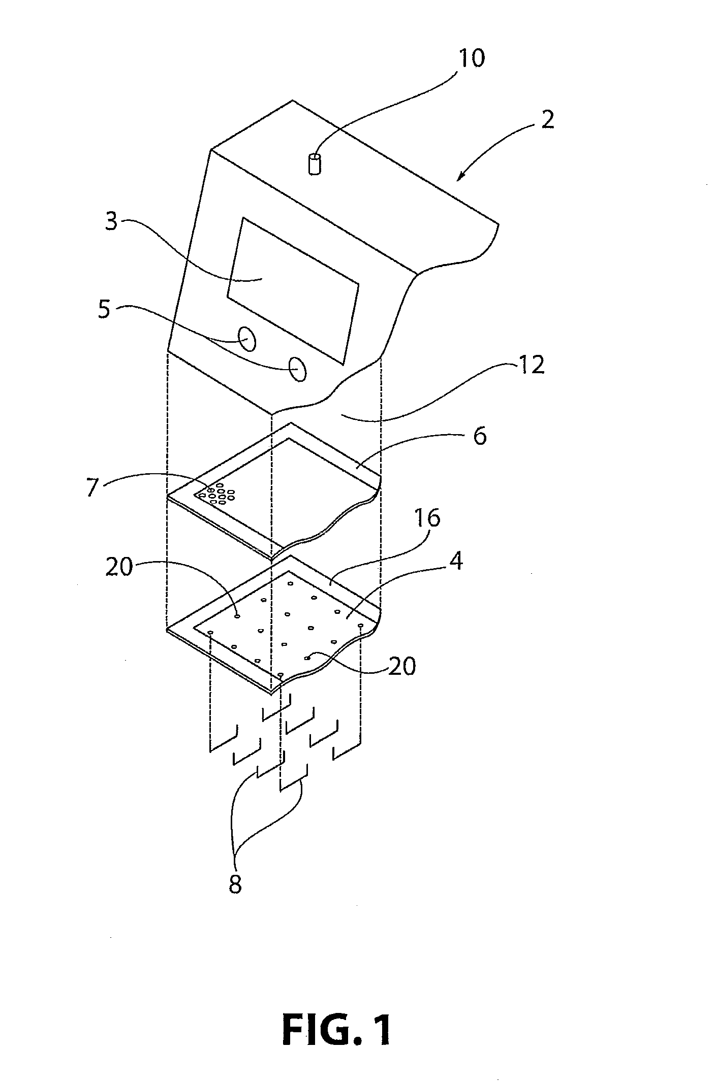
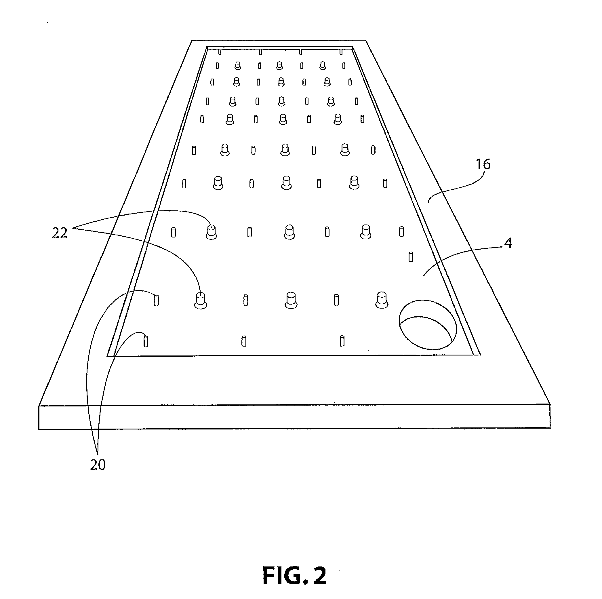
[0019]As shown in FIG. 1, the present invention not only recognizes the density difference between argon and air but also relies on the inert gas distribution system to provide a non-turbulent, laminar flow front of inert gas. This system is designed to provide for multiple inlets which rapidly distribute a large volume of inert gas such as argon at a low pressure across the entire chamber floor. This is accomplished by controlling pipe size and the addition of flow restriction diffuser devices to equalize the flow of all supply outlets. Also, the exhaust outlet must be sized to accommodate a high flow with minimal back pressure. This system can also be accompanied with a perforated plate system which protects piping outlets / flow restriction device, increases uniformity of gas flow, and also provides a stable working platform to support the workpiece to be welded, for example.

[0020]A presently preferred embodiment of the invention depicted in the drawings is directed to a welding ch...


PUM

PropertyMeasurementUnit
diameteraaaaaaaaaa
flow rateaaaaaaaaaa
pressureaaaaaaaaaa

Abstract

Apparatus and method for purging atmospheric air from a chamber with a gas including means for generating a substantially non-turbulent, laminar flow front of the gas into the chamber with minimal turbulence to displace the atmospheric air in the chamber, the chamber having exhaust means associated therewith to permit the displaced atmospheric air to exit the chamber. The chamber is preferably a welding chamber and the gas is preferably argon.

Description

CROSS REFERENCE TO RELATED APPLICATIONS[0001]This application is a division of U.S. patent application Ser. No. 12 / 903,502 filed Oct. 13, 2010, which claims priority to U.S. Provisional patent application No. 61 / 251,751 filed on Oct. 15, 2009, the entire contents of which are incorporated by reference herein.BACKGROUND OF THE INVENTION[0002]1. Field of the Invention[0003]The present invention relates generally to apparatus and methods for purging atmospheric air from an enclosed chamber, such as a welding chamber, and replacing the air with an inert gas.[0004]2. Description of Related Art[0005]In the manufacture / repair of complex investment cast shapes for aerospace, medical and land based systems markets, it is oftentimes necessary to perform a welding operation.[0006]For some alloys, particularly titanium alloys, there is a requirement to perform welding in a sealed chamber of argon. In this application, a part is loaded into a chamber and the air is removed by introducing argon t...

Claims


Application Information

Patent Timeline
Patent Type & Authority Applications(United States)
IPC IPC(8): B23K31/02B23K37/00
CPCB23K9/325B23K26/123
Inventor PATRICK, LEEBRAYSHAW, DAVIDWITTKOP, SCOTTBARRETT, JAMESLEI, TING-KWO
Owner PCC STRUCTURALS
Why Eureka
Try Eureka