Optical pickup device, optical disk device, and manufacturing method for the same
- Summary
- Abstract
- Description
- Claims
- Application Information
AI Technical Summary
Benefits of technology
Problems solved by technology
Method used
Image

Examples
first embodiment
Configuration of Optical Pickup Device
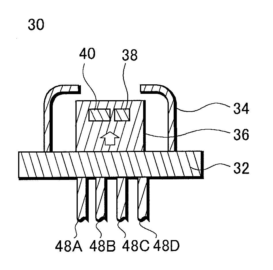
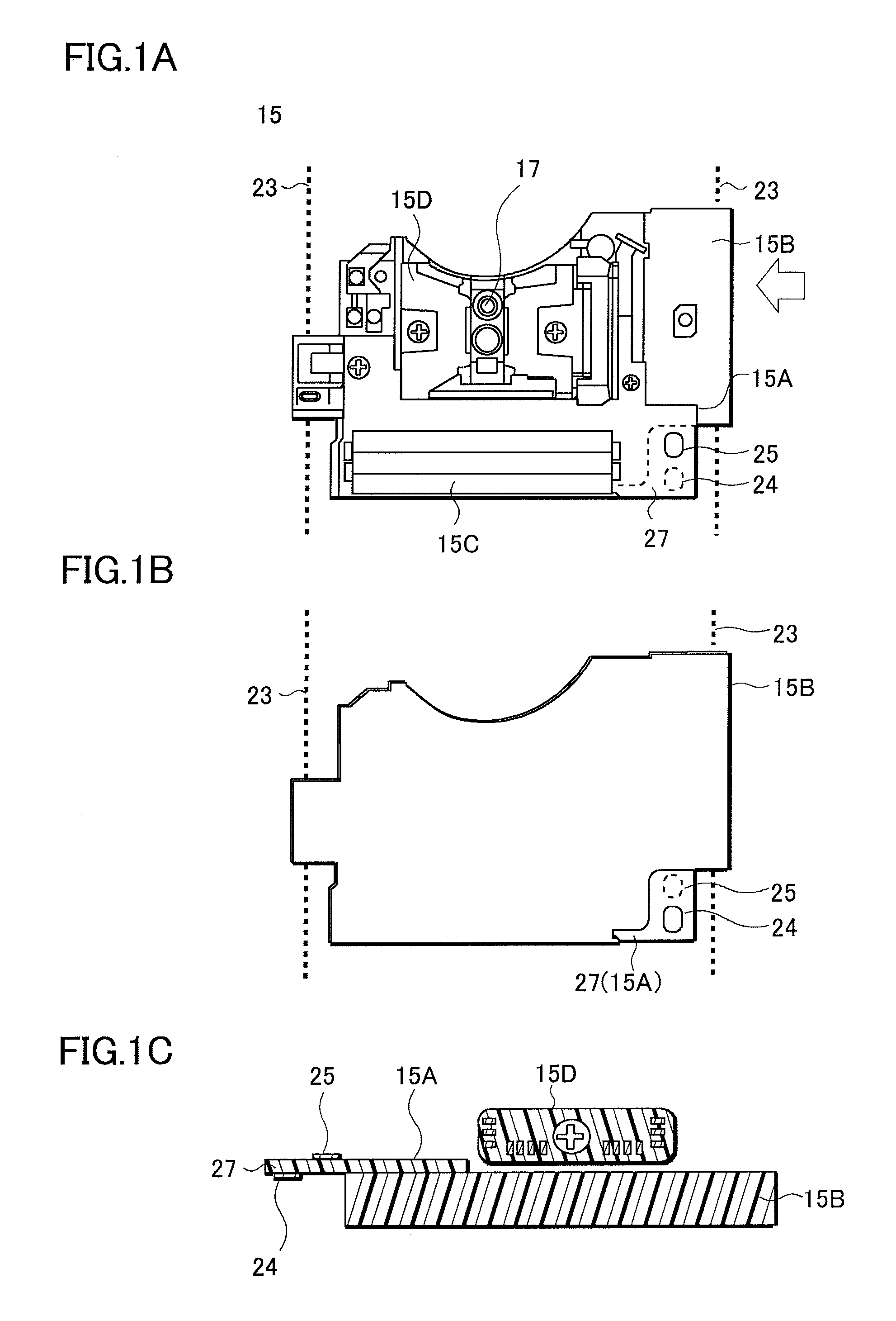
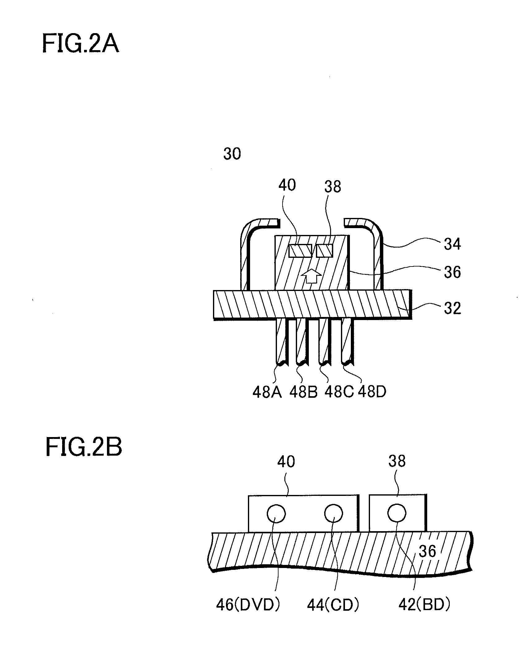
[0033]The configuration of an optical pickup device of the present embodiment is described with reference to FIGS. 1 to 4. FIG. 1 shows views of an optical pickup device 15; FIG. 2 shows views of a laser device which is incorporated in the optical pickup device; and FIGS. 3 and 4 are views of a short circuit portion which is an essential portion of the present embodiment.
[0034]First, the optical pickup device 15 is described with reference to FIG. 1. FIG. 1A is a plan view from above of the optical pickup device 15; FIG. 1B is a perspective view from above of the optical pickup device; and FIG. 1C is a side view (when viewed in the direction indicated by the arrow in FIG. 1A) of the optical pickup device. In the components of FIG. 1A, the front side of the drawing is referred to as a front surface, and the back side of the drawing is referred to as a back surface.
[0035]The optical pickup device 15 focuses a laser beam compliant with BD (Blu-ray...
second embodiment
Configuration of Optical Disk Device
[0072]The configuration of the optical disc device in which an optical pickup device having the above-described configuration is incorporated is described with reference to FIGS. 5 and 6. An optical disc device 10A illustrated in FIG. 5, and an optical disc device 10B illustrated in FIG. 6 are different with respect to the manner in which the optical pickup device 15 is exposed to the outside.
[0073]The optical disc device 10A is described with reference to FIG. 5. FIG. 5A is a cross-sectional view illustrating optical disc device 10A; and FIG. 5B is a plan view from above of the optical disc device 10A.
[0074]Referring to FIG. 5A, in the optical disc device 10A, a case 11 having an upper surface 11A and a lower surface 11B includes a main circuit board 18, a flexible printed circuit board 16, the optical pickup device 15, and the supporting axle 23 within the case 11.
[0075]The configuration of the optical pickup device 15 is the same as that descr...
third embodiment
Manufacturing Method of Optical Disk Device
[0097]In the present embodiment, a method of manufacturing optical disc devices is described based on the flowchart in FIG. 8 with reference to the above-described figures.
[0098]A method of manufacturing optical disc devices of the present embodiment includes: Step S11 of connecting a light emitting chip and a circuit board; Step S13 of assembling an optical pickup device; Step S15 of making an inspection and a adjustment of the optical pickup device; Step S17 of assembling the optical disc device; and Step S19 of making an adjustment with a device mechanism.
[0099]In the method of manufacturing optical disc devices of the present embodiment, assembly is performed by workers, and thus wiring is short-circuited using the above-described short circuit pin in a process in which static electricity may be discharged from the workers. Accordingly, the electrodes of the light emitting chips built in the optical pickup device are short-circuited vi...
PUM
 Abstract
Description
Claims
Application Information
 - R&D
- Intellectual Property
- Life Sciences
- Materials
- Tech Scout
- Unparalleled Data Quality
- Higher Quality Content
- 60% Fewer Hallucinations
Browse by: Latest US Patents, China's latest patents, Technical Efficacy Thesaurus, Application Domain, Technology Topic, Popular Technical Reports.
© 2025 PatSnap. All rights reserved.Legal|Privacy policy|Modern Slavery Act Transparency Statement|Sitemap|About US| Contact US: help@patsnap.com