
Ph sensor, ph measurement method, ion sensor, and ion concentration measurement method

a technology of ion sensor and ion concentration, applied in the field of ph sensor, can solve the problems of difficult use, contamination of liquid, and difficulty in accurate measuremen

Active Publication Date: 2012-08-09
YOKOGAWA ELECTRIC CORP
View PDF1 Cites 8 Cited by
  • Summary
  • Abstract
  • Description
  • Claims
  • Application Information

AI Technical Summary

Benefits of technology

The present invention provides a pH sensor and an ion sensor that overcome the problems of the reference electrode. The pH sensor includes a reference electrode and a working electrode, with the reference electrode including a p-channel field effect transistor (FET) having a diamond surface with hydrogen insensitive terminals. The ion sensor includes a reference electrode and a working electrode, with the reference electrode including a p-channel FET with a different semiconductor surface terminal. The diamond surface can be formed of hydrogen-terminated diamond or conductive diamond. The pH measurement method involves measuring pH based on the outputs of the reference electrode and the working electrode. The ion concentration measurement method involves measuring the concentration of ions based on the outputs of the reference electrode and the working electrode. The present invention provides a solution for accurate pH and ion measurements in extreme environments.

Problems solved by technology

In the glass electrode type pH sensor disclosed in Japanese Unexamined Patent Application, First Publication No. 1997(H09)-005290 or Japanese Unexamined Patent Application, First Publication No. 2007-078373, problems occur such as contamination of the liquid to be measured caused by leakage of the internal liquid, which is contained inside a layer of the holder in which the reference electrode is held, into the liquid to be measured, a change in state caused by moisture vaporization of the internal liquid, crystallization of the internal liquid, and the like.
As such, the SAM has a problem with physical and chemical instability in a high-temperature, high-pressure state of a chemical synthesis plant, or in a strong acid or alkaline process of a semiconductor fabricating process, and thus is difficult to use.
Further, in a bioprocess of handling bio-related materials such as proteins, the protein is adsorbed to the SAM, making accurate measurement difficult.

Method used


Image

  • Ph sensor, ph measurement method, ion sensor, and ion concentration measurement method
  • Ph sensor, ph measurement method, ion sensor, and ion concentration measurement method
  • Ph sensor, ph measurement method, ion sensor, and ion concentration measurement method

Examples


Embodiment Construction

[0052]The present invention will be now described herein with reference to illustrative preferred embodiments. Those skilled in the art will recognize that many alternative preferred embodiments can be accomplished using the teaching of the present invention and that the present invention is not limited to the preferred embodiments illustrated herein for explanatory purposes.

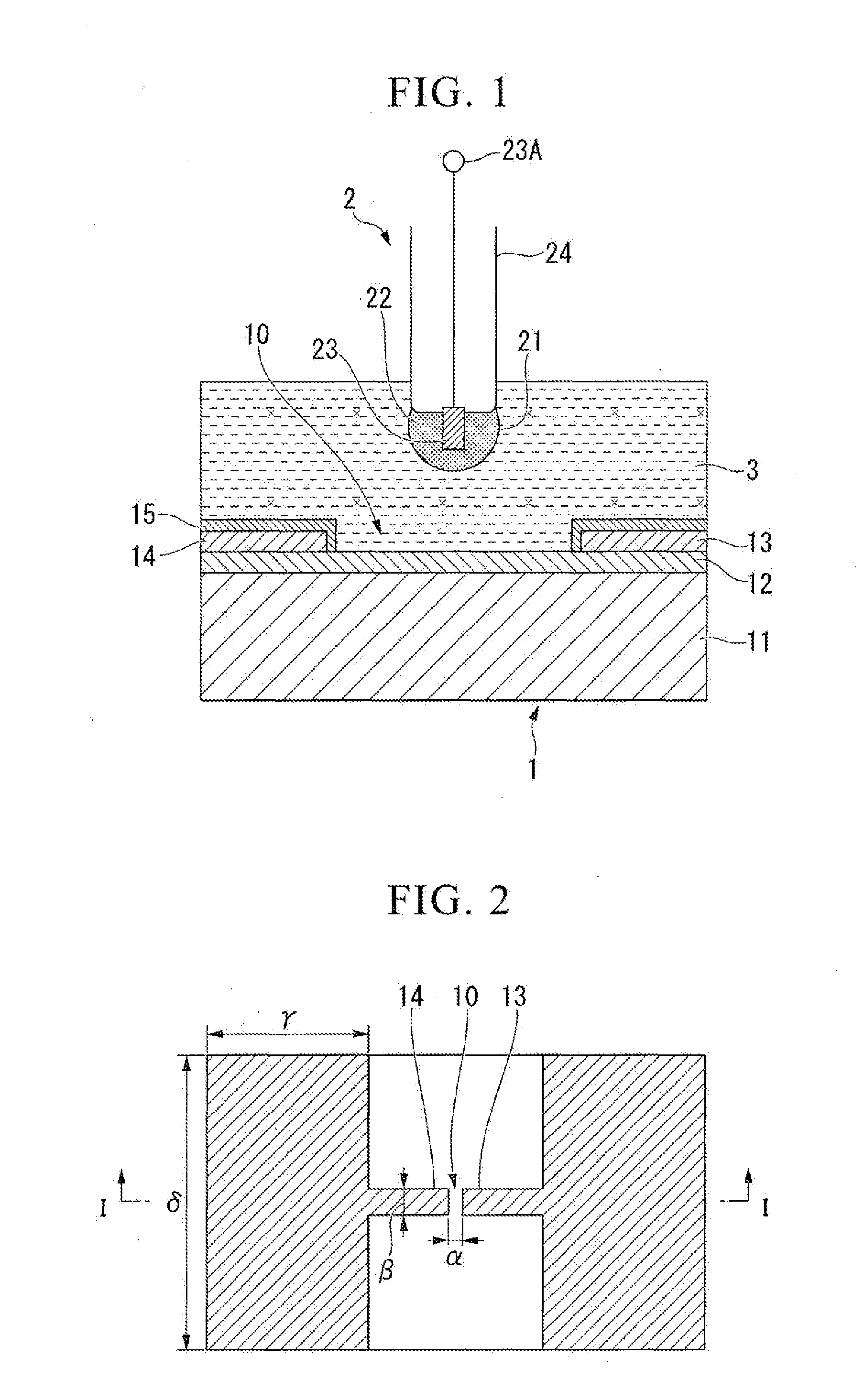
[0053]Hereinafter, reference will be made to a pH sensor in accordance with an preferred embodiment of the present invention. The pH sensor in accordance with an preferred embodiment of the present invention is an example in which a reference electrode based on a diamond ion sensitive FET (ISFET) as a p-channel field effect transistor (FET) is combined with a glass electrode in the present invention.

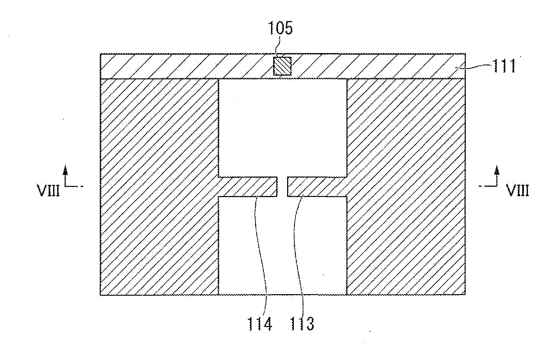
[0054]FIG. 1 is a cross-sectional view illustrating the construction of a pH sensor in accordance with a first preferred embodiment of the present invention. FIG. 2 is a plan view of an ISFET portion of the pH sensor...


PUM

PropertyMeasurementUnit
pHaaaaaaaaaa
widthaaaaaaaaaa
lengthaaaaaaaaaa

Abstract

A pH sensor may include a reference electrode including a p-channel field effect transistor (FET) whose gate includes a diamond surface having a hydrogen ion insensitive terminal, and a working electrode.

Description

BACKGROUND OF THE INVENTION[0001]1. Field of the Invention[0002]The present invention relates to a pH sensor for measuring the pH of a liquid to be measured based on outputs of a reference electrode and a working electrode.[0003]The present invention also relates to ion sensors, particularly a pH sensor among the ion sensors, for measuring an ion concentration of a liquid to be measured based on an output of a reference electrode and an output of a working electrode.[0004]Priority is claimed on Japanese Patent Application No. 2011-026194, filed Feb. 9, 2011, and Japanese Patent Application No. 2011-031102, filed Feb. 16, 2011, the contents of which are incorporated herein by reference.[0005]2. Description of the Related Art[0006]All patents, patent applications, patent publications, scientific articles, and the like, which will hereinafter be cited or identified in the present application, will hereby be incorporated by reference in their entirety in order to describe more fully the...

Claims


Application Information

Patent Timeline
Patent Type & Authority Applications(United States)
IPC IPC(8): G01N27/414
CPCG01N27/308G01N27/414
Inventor SHINTANI, YUKIHIROTAKENAKA, KAZUMA
Owner YOKOGAWA ELECTRIC CORP
Learn More