
Oscillator

a technology of oscillator and solder plate, which is applied in the field of oscillator, can solve the problems of solder cracks that are more likely to occur in large components than in small components, and certain circuit components cannot be reduced in size, so as to achieve simple structure, reduce solder cracks, and reduce the effect of cos

Inactive Publication Date: 2012-08-09
NIHON DEMPA KOGYO CO LTD
View PDF1 Cites 14 Cited by
  • Summary
  • Abstract
  • Description
  • Claims
  • Application Information

AI Technical Summary

Benefits of technology

[0051]The present invention was conceived in view of the above-mentioned circumstances, and has an object of providing an oscillator that can suppress a solder crack caused by a temperature change by a simple structure at low cost and improve heat cycle resistance performance.
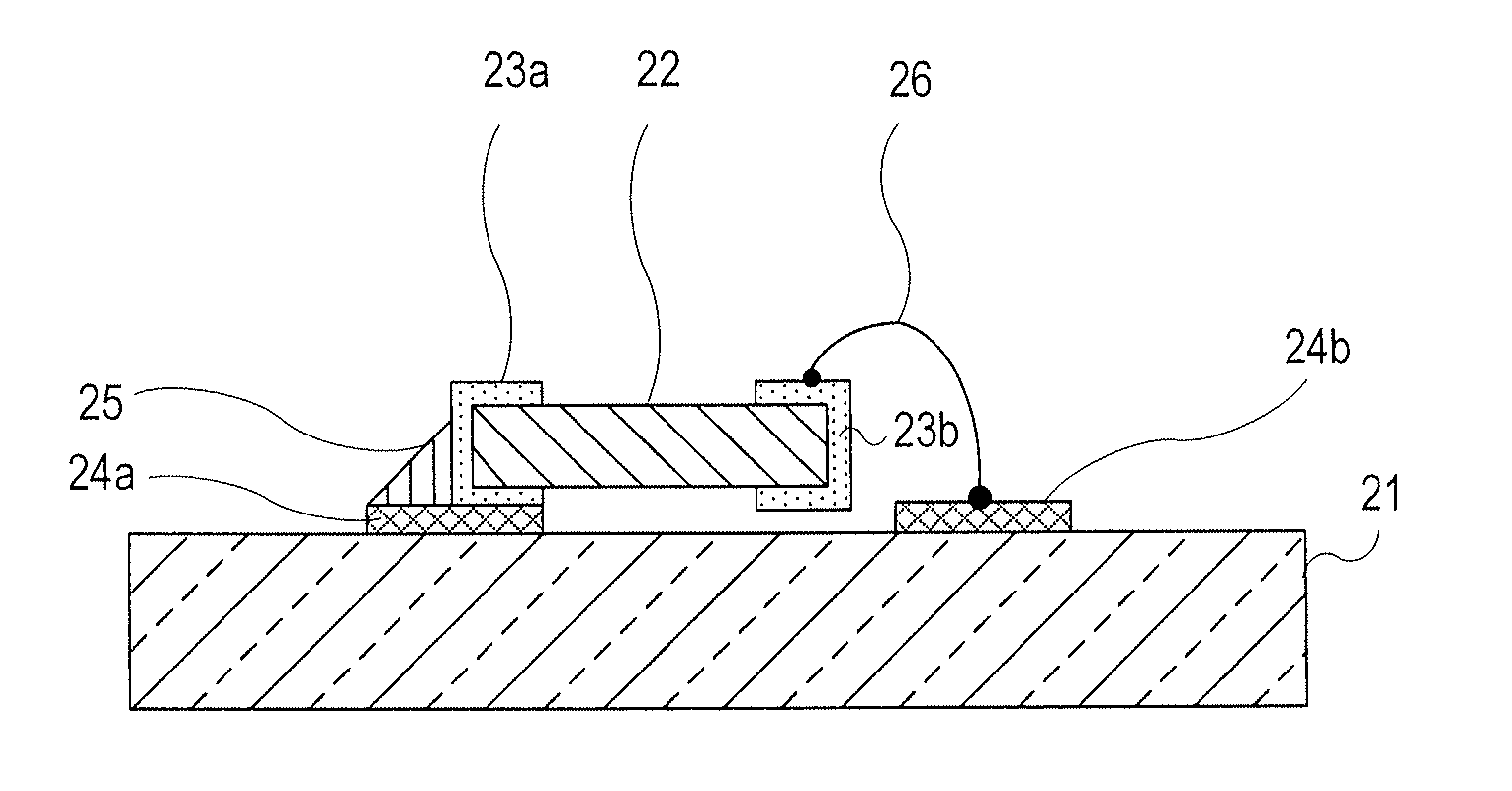
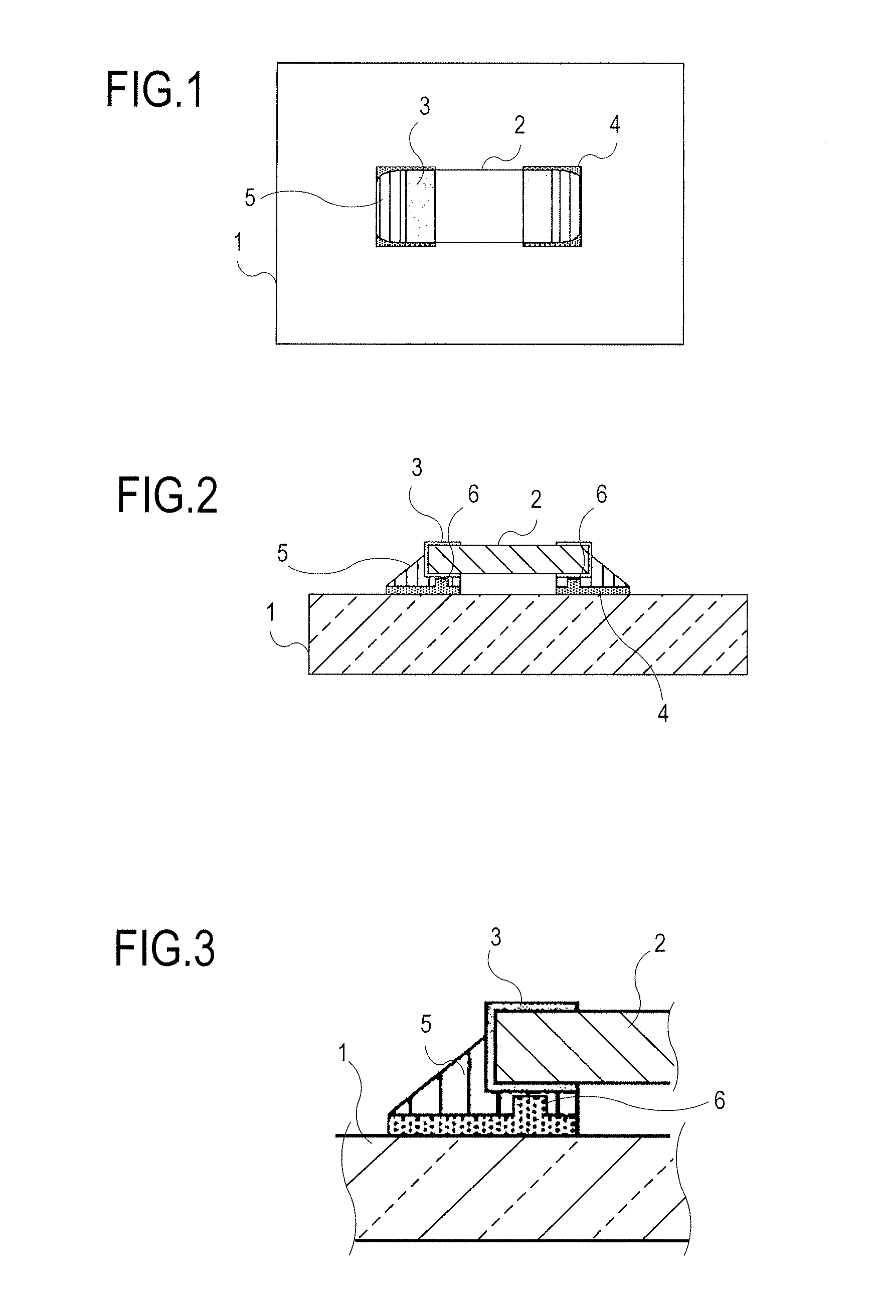
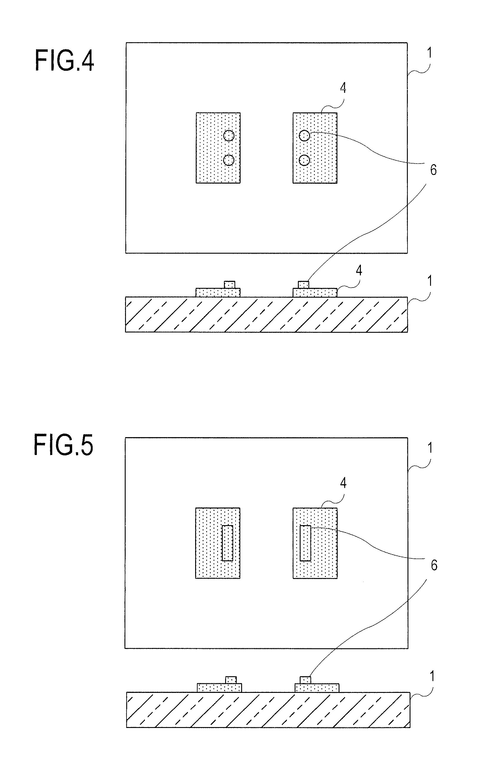
[0052]To solve the problems of the prior art stated above, the present invention is an oscillator (an oscillator according to a first group) including an epoxy resin board and a circuit component mounted on the board, the oscillator comprising: two-terminal electrode patterns formed on the board and solder-connected to terminal electrodes of the circuit component; a projection formed on each of the electrode patterns at a part of contact with a corresponding terminal electrode; and solder applied onto the electrode pattern, the solder being filled in a space between the electrode pattern and the terminal electrode and, as a result of reflow after the circuit component is mounted, forming a fillet between the electrode pattern and a side surface of the terminal electrode. This has an advantageous effect of strengthening adhesion by thick solder formation, suppressing a solder crack caused by a temperature change by a simple structure at low cost, and improving heat cycle resistance performance.

Problems solved by technology

However, the above-mentioned conventional oscillator has a problem that, due to a difference in thermal expansion coefficient between the electronic component (circuit component) using ceramic or the like and the glass epoxy resin circuit board, strain concentrates on the mount solder in a use environment where a heat cycle occurs, causing a crack in the solder.
It is commonly known that a solder crack is more likely to occur in large components than in small components.
However, certain circuit components cannot be reduced in size because of their performance or constants, and so there are many cases where large circuit components need to be used.
Especially in an oven controlled crystal oscillator (OCXO), in a use environment where power on / off is repeated, a temperature change from an ambient temperature to an oven control temperature (e.g. 85° C.) is added at each instance of power on / off, which induces a crack in solder.
Thus, there is a problem with long-term reliability.
Thus, Patent Document 4 fails to disclose a structure of easily lifting the electronic components by exploiting a normal circuit board manufacturing process.
Patent Document 6 discloses that a crystal chip is fixed to two support sections on a substrate, and so does not address substrate expansion and contraction caused by a temperature change.
However, these techniques require complex conditions and structures, and are unable to suppress a solder crack caused by a temperature change by a simple structure at low cost.

Method used


Image

  • Oscillator
  • Oscillator
  • Oscillator

Examples


application example

[Embodiment of Application Example]

[0161]An application example of the above-mentioned oscillator is described below.

[0162]In the application example, the two-terminal electrode patterns 4 on which the electronic component 2 is mounted are arranged so as to face each other in a direction same as a direction in which the glass epoxy resin board 1 has a smallest linear expansion coefficient.

[0163]In the case of a typical CEM-3 board as the board 1, the linear expansion coefficient is 25 ppm / ° C. in a longitudinal direction, 28 ppm / ° C. in a lateral direction, and 65 ppm / ° C. in a thickness direction.

[0164]In the case of a typical FR-4 board, the linear expansion coefficient is 13 ppm / ° C. in the longitudinal direction, 16 ppm / ° C. in the lateral direction, and 60 ppm / ° C. in the thickness direction.

[0165]Meanwhile, the linear expansion coefficient of ceramic (alumina) of the electronic component 2 is, for example, about 7 ppm / ° C.

[0166]Here, the long-scale direction of the board 1 is ...


PUM

PropertyMeasurementUnit
Expansion enthalpyaaaaaaaaaa

Abstract

An oscillator that can suppress a solder crack caused by a temperature change by a simple structure at low cost and improve heat cycle resistance performance is provided. The oscillator includes an epoxy resin board and an electronic component mounted on the board. Two-terminal electrode patterns are formed on the board, and connected to terminal electrodes of the electronic component by solder. A projection is formed on each of the electrode patterns at a part connected to a corresponding terminal electrode to create a space between the terminal electrode and the electrode pattern, and the solder forms a fillet in the space. This contributes to enhanced adhesion strength of the solder.

Description

[0001]This application has a priority of Japanese no. 2011-023575 filed Feb. 7, 2011, no. 2011-028223 filed Feb. 14, 2011, no. 2011-068064 filed Mar. 25, 2011 and no. 2011-152916 filed Jul. 11, 2011, hereby incorporated by reference.BACKGROUND OF THE INVENTION[0002]1. Field of the Invention[0003]The present invention relates to an oscillator using a circuit board of a glass epoxy resin, and particularly relates to an oscillator that relaxes strain on solder and improves heat cycle resistance performance.[0004]2. Description of the Related Art[Prior Art][0005]Conventionally, there is a crystal oscillator that uses a glass epoxy resin in a circuit board. Metal electrode patterns are formed on the circuit board, and an electronic component of ceramic or the like is mounted on the electrode patterns by soldering.[Conventional Crystal Oscillator: FIG. 22][0006]A conventional crystal oscillator is described below, with reference to FIG. 22. FIG. 22A is a plan view of the conventional crys...

Claims


Application Information

Patent Timeline
IPC IPC(8): H03B5/32H05K3/34
CPCH05K1/111H05K3/3442H05K2201/09781Y10T29/49144H05K2201/2036H03B5/32Y10T29/42H05K2201/10075Y02P70/50H03H9/10H03H9/13
Inventor NISHIYAMA, DAISUKEKASAHARA, KENJIMURAKOSHI, HIROYUKI
Owner NIHON DEMPA KOGYO CO LTD
Learn More