Method for dilating between spinous processes

a spinous process and process technology, applied in the field of dilating between spinous processes, can solve the problems of intermittent claudication, difficult fixation, lumbar spondylolysis, etc., and achieve the effect of effectively reducing the symptoms of these diseases and effectively treating them

Inactive Publication Date: 2012-08-16
TERUMO KK
View PDF30 Cites 5 Cited by
  • Summary
  • Abstract
  • Description
  • Claims
  • Application Information

AI Technical Summary

Benefits of technology

[0013]By the method according to an embodiment of the present invention, it is possible to effectively treat cervical spinal disk herniation, cervical spondylosis, ossification of posterior longitudinal ligament, lumbar disk h

Problems solved by technology

When a load is repeatedly exerted on the lumbar spine due to sports or the like to cause a fatigue fracture, there would result lumbar spondylolysis in which the lumbar spines are separated at the vertebral arch part or lumbar degenerated spondylolisthesis in which it becomes difficult to fix the upper lumbar spine due to degeneration of the intervertebral disk or the shape of the facet joint and a slip-off of the lumbar spines is thereby caused.
Further, a severe slip of lumbar spines may cause stenosis of the vertebral canal, possibly leading to intermittent claudication, which is a symptom of lumbar spinal canal stenosis.
In the case of a fracture of a facet joint, such as lumbar degenerative spondylolisthesis and lumbar spondylolysis, there is a high possibility of postoperative instability, which needs fixation (fusion).
A patient with lumbar degenerative spondylolisthesis or lumbar spondylolysis should be hospitalized for an average of about 60 days, in general; in addition, this technique inevitably involves general anes

Method used


Image

  • Method for dilating between spinous processes
  • Method for dilating between spinous processes
  • Method for dilating between spinous processes

Examples


example 1

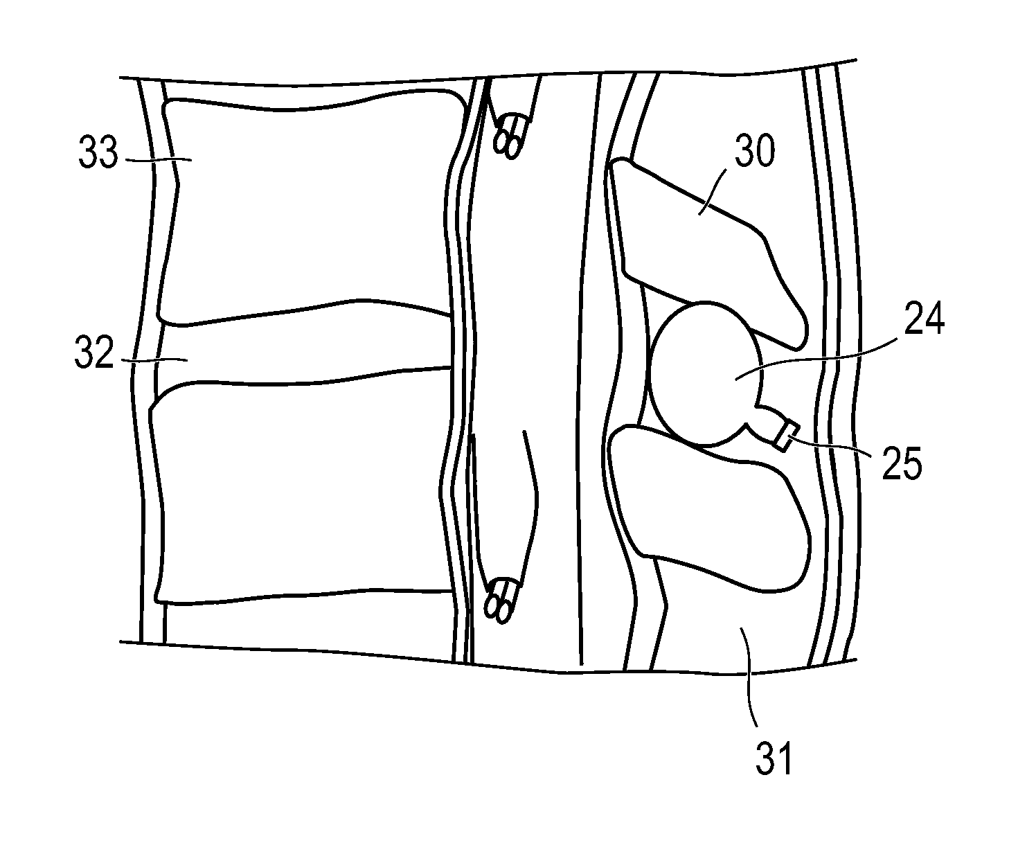
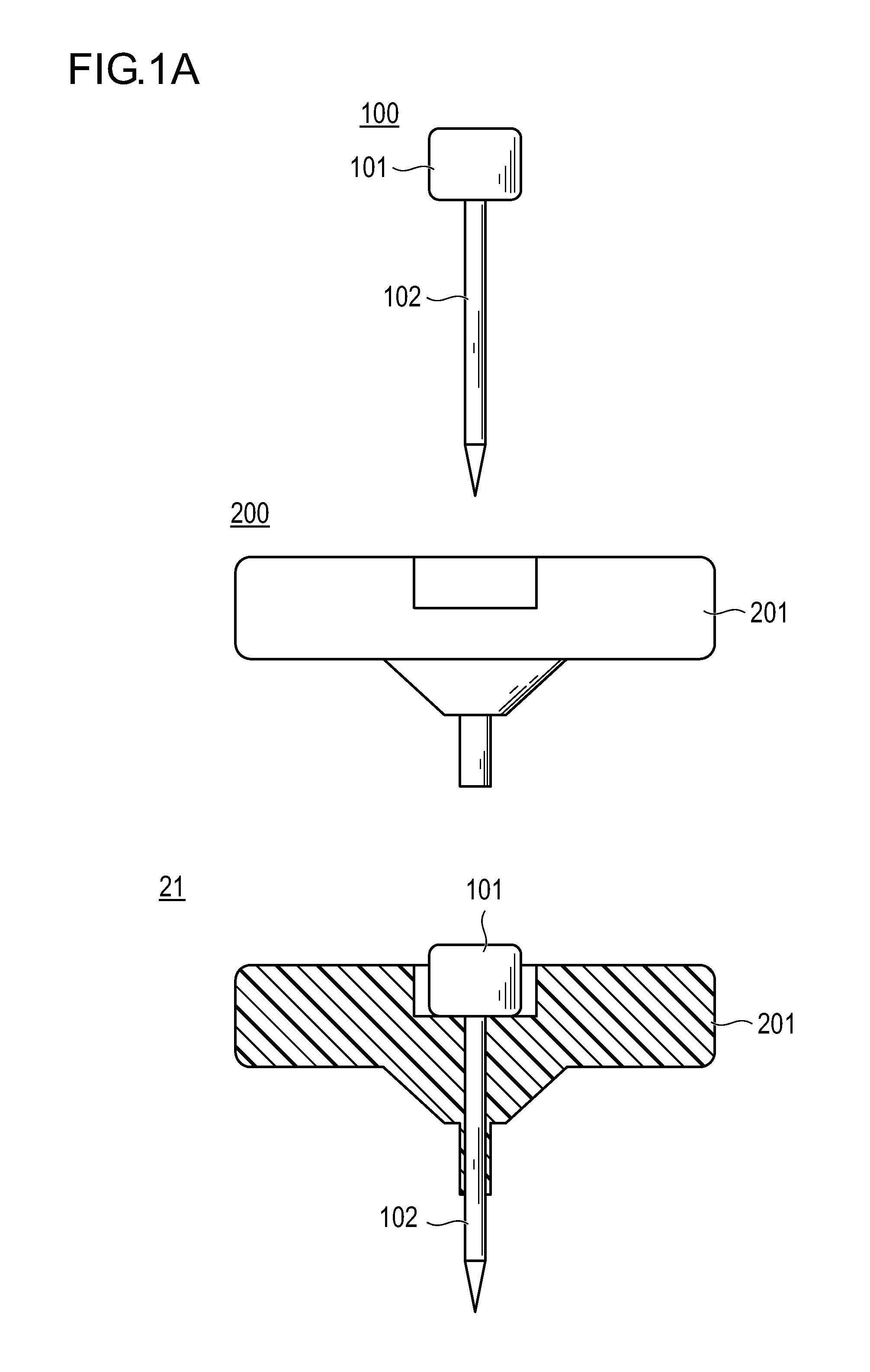
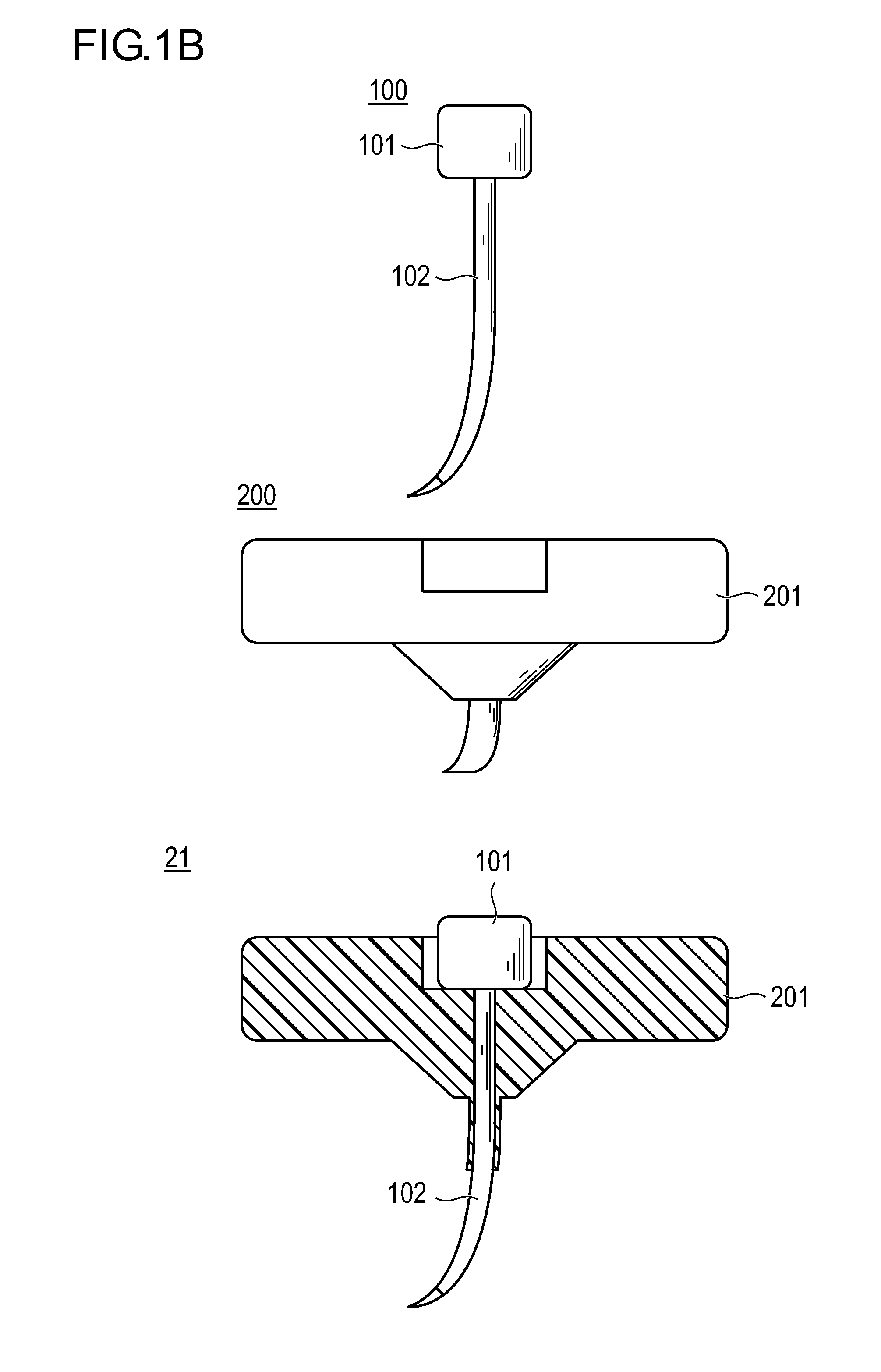
[0161]First, after the lesion is determined by roentgen or MRI technique, the part to be treated is anesthetized by local anesthesia or lumbar anesthesia. Then, the patient is put into prone position or lateral position, and the body is bent as much as possible, whereby the area between spinous processes 30 on the rear side of the vertebral body 33 and the intervertebral disk 32 is widened. Next, an approach site 11 for locating the expansion body is marked on the upper skin corresponding to the part between the spinous processes 30 which is the part to be treated (FIG. 5). Two puncture needles 21 having an inside diameter of 1 to 5 mm are made to penetrate the marked part by about 1 to 2 cm from the skin until they reach the paravertebral muscle. Then, the inner needles of the puncture needles 21 are pulled out, and the outer tubes of the puncture needles 21 are put locating (FIG. 6).

[0162]Rongeurs 22 as shears devices are inserted respectively into the lumens of the two puncture n...

example 2

[0167]After the same technique as in Example 1 is conducted and the contrast agent and the like are discharged from the expansion body 24 as much as possible, a hardening material being fluid at the time of injection and hardening after the injection is injected as a filling material into the filamentous body 23 provided with the expansion body, to expand the expansion body (FIG. 13).

[0168]Next, the puncture needle 21 is evulsed from the skin, and the shaft 26 of the filamentous body 23 provided with the expansion body is exposed. The filamentous body 23 provided with the expansion body is pulled proximally to such an extent that the expansion body 24 is not pulled off, whereby the injection port 25 of the expansion body 24 is elongated by 0.2 to 1 cm. Then, the injection port 25 is tied with a twisted suture or a band or the like on the outside of the skin, to be sealed (FIG. 14). Further, the filamentous body portion on the proximal side of the seal is resected by use of scissors....

example 3

[0169]In the same manner as in Example 1, after the lesion is determined by roentgen or MRI technique, the part to be treated is anesthetized by local anesthesia or lumbar anesthesia, the patient is put into prone position or lateral position, and the body is bent as much as possible, to widen the area between the spinous processes 31. Next, marking of one approach site for placement of the expansion body is made on the upper skin corresponding to the part between the spinous processes 30 which is to be treated. A puncture needle 21 having an inside diameter of 1 to 5 mm is made to puncture the marked part to a depth of about 1 to 2 cm from the skin, until it reaches the paravertebral muscle 31. Then, the inner needle of the puncture needle 21 is pulled out, and the outer needle of the puncture needle 21 is located (FIG. 17).

[0170]A rongeur 22 is inserted into the lumen of the puncture needle 21. While holding down the puncture needle 21, cutting 41 of the interspinal ligament 31 to...


PUM


Abstract

Disclosed is a method for dilating between spinous processes wherein a filamentous body provided with an expansion body is percutaneously inserted to locate the expansion body between the spinous processes, a filling material is injected into the expansion body to dilate between the spinous processes, and the expansion body is cut off from the filamentous body to be located between the spinous processes. This method exerts very little burden on the patient.

Description

BACKGROUND[0001]1. Technical Field[0002]The present invention relates to a method for dilating between spinous processes.[0003]2. Description of the Related Art[0004]A lumbar spine has a vertebral body as a front half and a vertebral arch as a rear half which are interconnected through a pedicle of vertebral arch, with the vertebral arch formed with processes such as a spinous process, a mamillary process and an accessory process, and normally has a slightly forwardly curved shape. In addition, since adjacent lumbar spines are interconnected through an intervertebral disk, a certain lumbar spine and the adjacent spine, for example, are prevented by an intervertebral disk and a facet joint from getting out of alignment with each other. When a load is repeatedly exerted on the lumbar spine due to sports or the like to cause a fatigue fracture, there would result lumbar spondylolysis in which the lumbar spines are separated at the vertebral arch part or lumbar degenerated spondylolisth...

Claims


Application Information

Patent Timeline
IPC IPC(8): A61B17/70A61B17/88
CPCA61B17/320016A61B17/3201A61B2017/3454A61B17/7097A61B17/8816A61B17/3468A61B17/7065A61B17/8827A61B2017/00557
Inventor HATA, SUGURUNAKAGAWA, YUJITADA, YUICHIKINOSHITA, YASUSHI
Owner TERUMO KK
Why Eureka
Try Eureka