Photovoltaic strip solar modules and methods

a technology of photovoltaic strip and solar modules, applied in the direction of sustainable manufacturing/processing, instruments, final product manufacturing, etc., can solve the problems of increased thickness of solar panels, loss of reflecting capability, exposed metal corroding, etc., and achieve greater angle of incidence capability and solar efficiency increase

Inactive Publication Date: 2012-08-23
SOLARIA CORP
View PDF3 Cites 32 Cited by
  • Summary
  • Abstract
  • Description
  • Claims
  • Application Information

AI Technical Summary

Benefits of technology

[0011]In various embodiments, the characterization data may be used as input for a PV strip placement operation with respect to the sheet of material. For example, such characterization data may be used by a user to determine where to place a PV strip relative to the sheet of material in an x and y direction, as well as a θ direction. As another example, such characterization data may be used by a machine or device that can pick PV strips and accurately position the PV strip relative to the sheet of material. In various embodiments, the placement of the PV strip relative to the sheet of material maximizes the capture of solar light by the PV strip. In other embodiments, the placement allows a wider angle of incidence of solar light striking the PV panel that is captured by the PV strips. Additionally, in various embodiments, the placement may be modified based upon physical properties such as: conductive bus bar expansion and contraction, reflow of material during a lamination step, or the like
[0013]Previously, with solar panels, much emphasis has been placed upon uniformity. For example, uniform placement of solar wafers within a solar panel, uniform placement of solar cells within a mirror concentrator, and the like. The inventors of the present invention has discovered that uniformity is not always desirable. Further, the inventors have discovered that by modifying placement locations of PV strips within a PV assembly or PV string may desirable. For example, by determining variations in physical properties of solar concentrators, locations of PV strips may be placed in expressly non-uniform locations. Unexpectedly, the inventors have realized an solar efficiency increase of a PV panel manufactured according to embodiments described herein. Further, the inventors have realized a greater angle of incidence capability of such a PV panel. Accordingly, embodiments described herein provide unexpected benefits.

Problems solved by technology
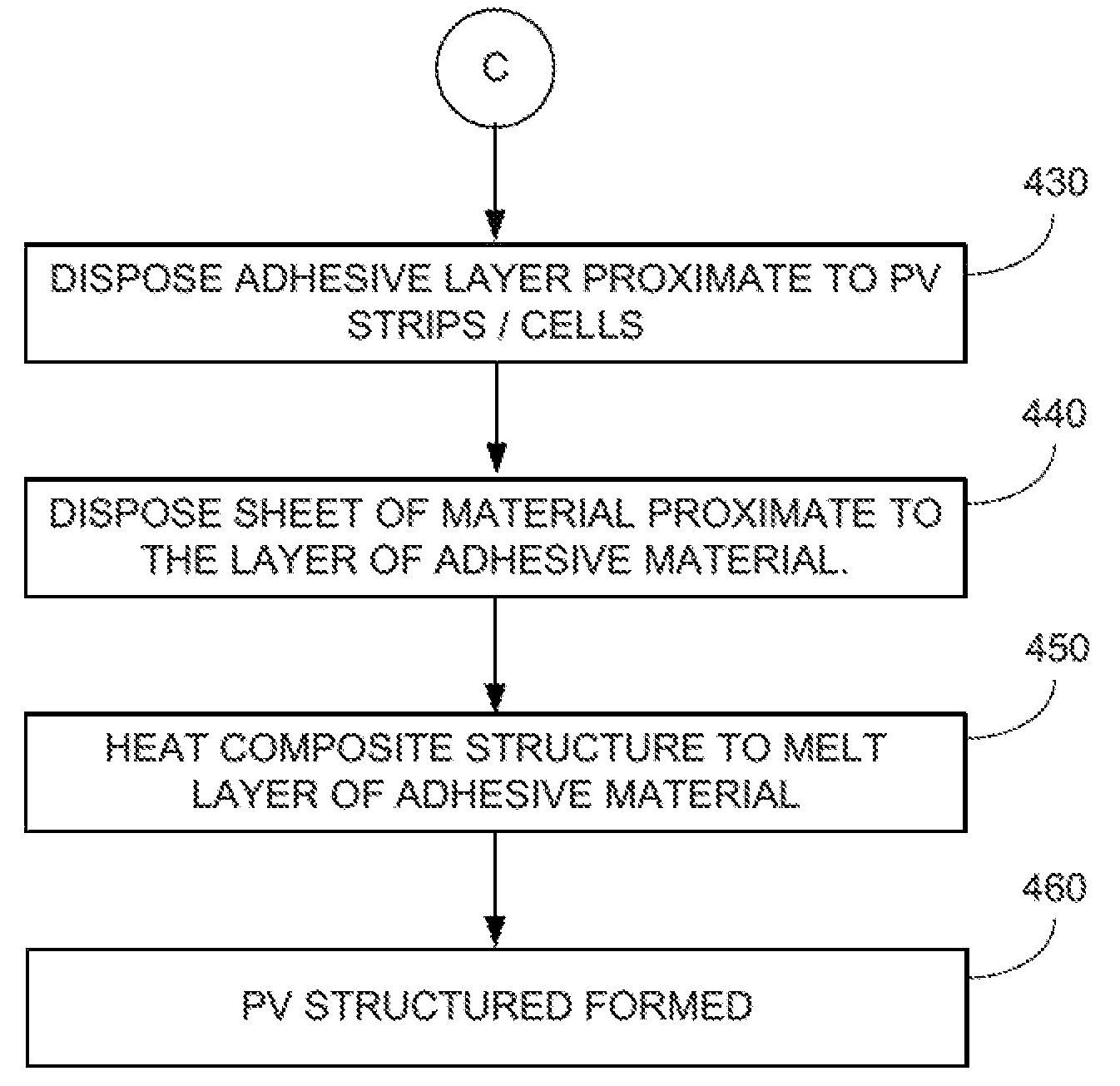
Another challenge is how to manufacture such solar concentrators with materials that can last the expected life span of a solar panel, or the like, e.g. over 20 years.
Drawbacks to such solutions include that a metal concentrator would be bulky and would cause the thickness of the solar panel to increase greatly.
Another drawback includes that exposed metal may corrode and lose reflecting capability as it ages.
One possible drawback to such solutions considered by the inventor is the durability and longevity of such polycarbonate layers.

Method used


Image

  • Photovoltaic strip solar modules and methods
  • Photovoltaic strip solar modules and methods
  • Photovoltaic strip solar modules and methods

Examples


Embodiment Construction

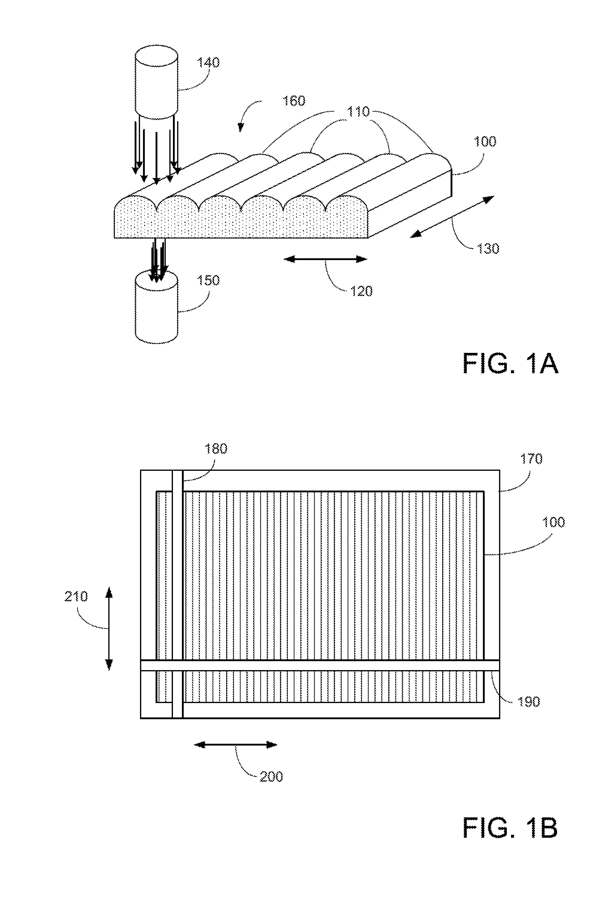
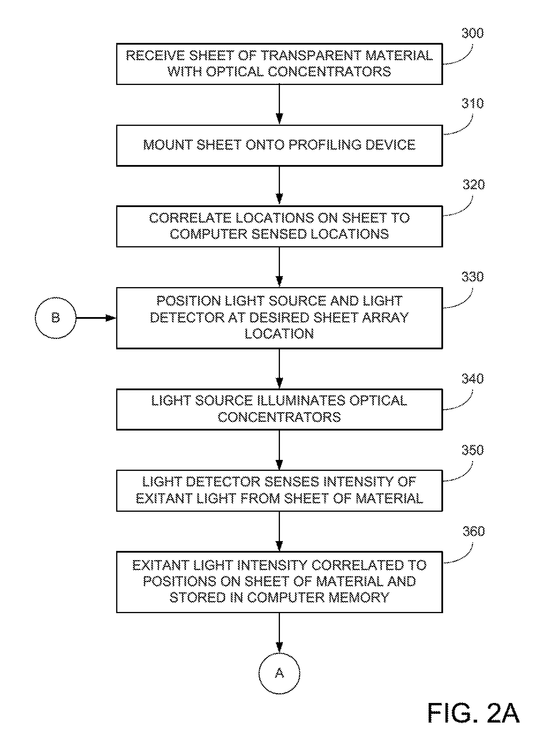
[0024]FIGS. 1A-B illustrate various aspects according to embodiments of the present invention. More specifically, FIGS. 1A-B illustrate an apparatus for determining concentration characteristics of a sheet of material 100.

[0025]In FIG. 1A, an embodiment of a sheet of transparent (substantially transparent) material 100 is shown. In some embodiments, the sheet may be translucent. As can be seen, sheet 100 may include a number of concentrating elements 110 in a first direction 120. In one example, there are approximately 175 concentrating elements across sheet 100, although in other examples, the number of concentrating elements may vary. In various examples, the nominal pitch of concentrating elements 110 ranges from approximately 5.5 mm to 6 mm. In other embodiments, the nominal pitch may be 5.74+ / −0.2 mm, 7.0+ / −0.2 mm, or the like. In various embodiments, as the nominal pitch increases, fewer PV strips, described below, are required for PV assemblies or PV strings.

[0026]In various ...


PUM


Abstract

A light energy collection device includes a glass layer having light concentrators for receiving light and for concentrating concentrated light, the light concentrators are elongated and substantially parallel manner to a first edge of the glass layer, wherein pitches of the light concentrators vary along the length generally within the range of approximately 5.5-5.8 mm, strings of multiple PV strips extending in a parallel manner to a second edge (perpendicular to the first edge) of the glass layer, wherein a string of PV strips includes: electrodes extending substantially parallel to the second edge, PV strips electrically coupled to the electrodes and extending substantially parallel to the first edge, wherein pitches of the PV strips vary along their length according to varying pitches of the light concentrators, wherein the PV strips receive concentrated light and output electrical energy in response to the concentrated light.

Description

CROSS REFERENCE TO RELATED APPLICATIONS[0001]This application claims priority to provisional application 61 / 502,282, filed Jun. 28, 2011, which is incorporated by reference for all purposes.BACKGROUND OF THE INVENTION[0002]The present invention relates to photovoltaic energy sources. More particularly, the present invention relates to using photovoltaic (PV) modules to convert solar energy into electrical energy.[0003]The inventor of the present invention has determined that a challenge with using PV strips for capturing solar energy is how to effectively direct and concentrate incident light / radiation to PV strips within a PV module. Another challenge is how to manufacture such solar concentrators with materials that can last the expected life span of a solar panel, or the like, e.g. over 20 years.[0004]One possible solution considered by the inventor was with the use of a metal concentrator in front of PV strips within a PV module. Drawbacks to such solutions include that a metal ...

Claims


Application Information

Patent Timeline
Patent Type & Authority Applications(United States)
IPC IPC(8): H01L31/052
CPCH01L31/0543Y02E10/52G02B3/005H01L31/1876Y02P70/50
Inventor MARATHE, AJAYBATTAGLIA, JR., DOUGLAS R.MAGANA, FRANKCHAWARE, RAGHUNANDAN
Owner SOLARIA CORP
Why Eureka
Try Eureka