
Method for Manufacturing A Micro Tube Heat Exchanger

a technology of heat exchanger and micro-tube, which is applied in the direction of manufacturing tools, soldering devices, light and heating equipment, etc., can solve the problems of identifying and patching tens or hundreds of leaks, and increasing the cost and time of hole drilling, so as to achieve enhanced heat transfer/pressure drop ratio, increased heat exchange area per unit volume, and improved heat exchange coefficient

Inactive Publication Date: 2012-08-23
INT MEZZO TECH
View PDF0 Cites 12 Cited by
  • Summary
  • Abstract
  • Description
  • Claims
  • Application Information

AI Technical Summary

Benefits of technology

This method significantly reduces manufacturing costs and time, achieving a high success rate of leak-free seals, essential for the commercial viability of micro tube heat exchangers.

Problems solved by technology

However, a challenging component in manufacturing micro tube heat exchangers is the manufacture of the header plates and / or mid plates.
This process has been used successfully to fabricate heat exchangers, but it is expensive since the time and resources required to drill thousands to millions of holes in each of the header plates and mid plates is significant.
Furthermore, when structural loads dictate that the header must be relatively thick (greater than about five times the hole diameter), the process to drill holes becomes substantially longer.
If the application requires hard-to-drill materials such as 304 stainless steel, a nickel alloy such as INCONEL®, or titanium (as opposed to an easy-to-drill material such as many aluminum alloys), hole drilling is even more expensive and time consuming.
Another challenging component in manufacturing micro tube heat exchangers is the process of joining the thousands, tens of thousands, or millions of micro tubes to the header plates.
Identifying and patching tens or hundreds of leaks would be time consuming and expensive.
Still yet another challenging component of the manufacture of micro tube heat exchangers is the process by which tubes are inserted.
For the case of micro tube heat exchangers, the problem associated with tube insertion cost is magnified greatly because the number of tubes is extremely high, even for relatively small, mass produced products.

Method used


Image

  • Method for Manufacturing A Micro Tube Heat Exchanger
  • Method for Manufacturing A Micro Tube Heat Exchanger
  • Method for Manufacturing A Micro Tube Heat Exchanger

Examples


Embodiment Construction

[0033]Illustrative embodiments of the invention are described below as they might be employed in the method of manufacturing a heat exchanger according to the present invention. It will be of course appreciated that in the development of an actual embodiment, numerous implementation-specific decisions must be made to achieve the developers' specific goals, such as compliance with system-related and business-related constraints, which will vary from one implementation to another. Moreover, it will be appreciated that such a development effort might be complex and time-consuming, but would nevertheless be a routine undertaking for those of ordinary skill in the art having the benefit of this disclosure.

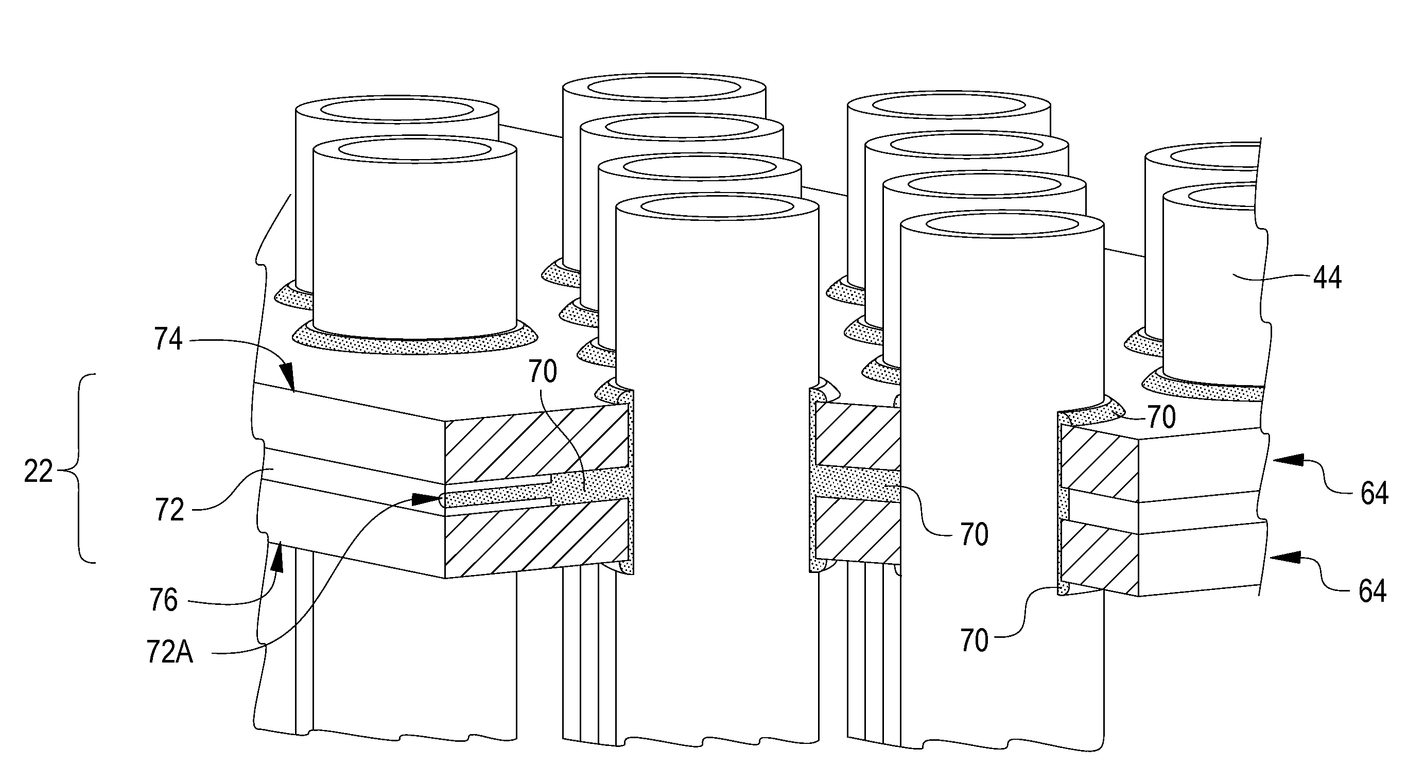
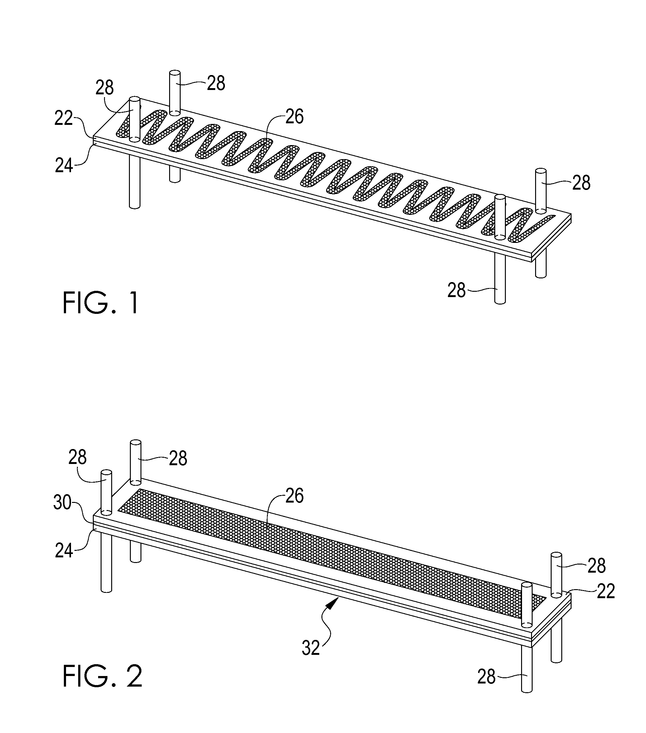
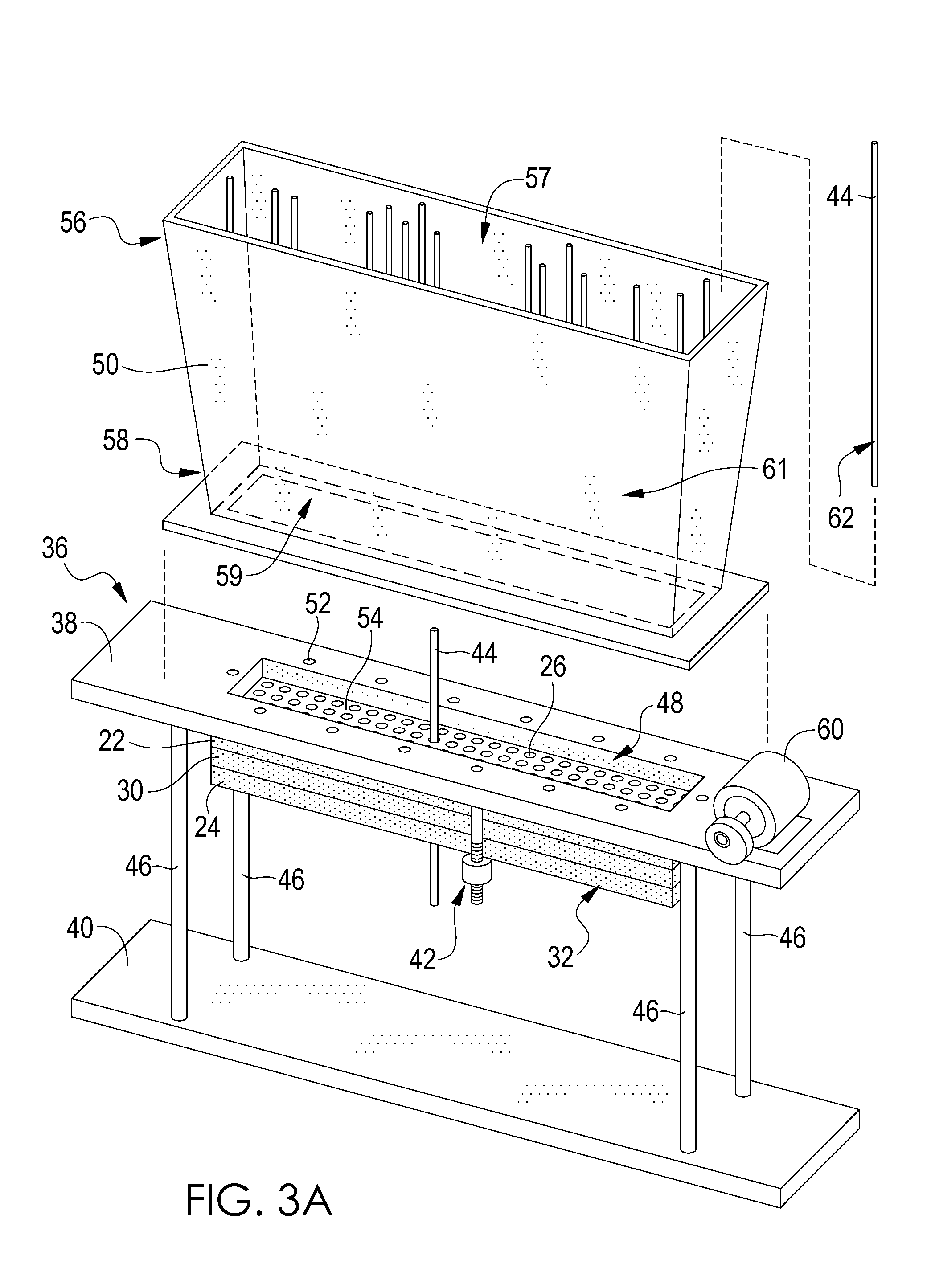
[0034]Turning now to the Figures, one embodiment of the present invention includes a method for manufacturing a heat exchanger component 20 as shown in FIG. 9. As shown in FIG. 1, in at least one embodiment, two end plates may be provided wherein the end plates provided are a first end ...


PUM

PropertyMeasurementUnit
diametersaaaaaaaaaa
diametersaaaaaaaaaa
diametersaaaaaaaaaa

Abstract

Method for fabricating a heat exchanger which, in one aspect, includes providing a stack of a plurality of lamina each of which defines a pattern of lamina apertures, the apertures being substantially alignable in the stack; disposing a plurality of microtubes through respective aligned lamina apertures extending through and defined by the stack of lamina so as to form a subassembly, a clearance existing between each of the microtubes and their respective aligned apertures when the microtubes are so disposed; and adhering together the lamina in the stack and the plurality of microtubes so disposed while forming a seal at the clearances.

Description

REFERENCE TO RELATED APPLICATIONS[0001]This application is a divisional of co-pending U.S. application Ser. No. 12 / 540,985, which claims the benefit of the priorities of U.S. Provisional Application No. 61 / 156,385, filed on Feb. 27, 2009, and U.S. Provisional Application No. 61 / 224,002 filed on Jul. 8, 2009, the disclosures of which are incorporated herein by reference.[0002]The U.S. Government has provided support for the making of, and has certain rights in, this invention as provided for by the terms of Contract No. N68335-08-0127 awarded by the U.S. Department of the Navy.TECHNICAL FIELD[0003]This invention relates to a method for manufacturing heat exchangers, particularly heat exchangers comprising micro tubes.SUMMARY OF THE INVENTION[0004]Heat exchangers are used to transfer energy from one fluid to another. Heat exchangers are typically characterized by heat transfer rates between fluids and corresponding pressure drops of the fluid(s) across the heat exchanger. Examples of ...

Claims


Application Information

Patent Timeline
Patent Type & Authority Applications(United States)
IPC IPC(8): B32B37/12B23K31/02
CPCB21D53/02B21D53/08F28D1/05333F28D7/16F28F9/0131Y10T29/4935F28F9/18F28F2260/02F28F2275/04Y10T156/10F28F9/162
Inventor BECNEL, CHARLES J.MCLEAN, JEFFREY J.
Owner INT MEZZO TECH
Learn More