
Container Candle with Enhanced Candle Performance and Candle Insert for Container Candle

a container candle and candle technology, applied in the field of container candle inserts, can solve the problems of inefficient combustion and disruption of flames, and achieve the effects of improving burn control, accelerating the delivery of active scent, and enhancing the performance of candles during burning

Inactive Publication Date: 2012-08-23
YANKEE CANDLE COMPANY
View PDF8 Cites 5 Cited by
  • Summary
  • Abstract
  • Description
  • Claims
  • Application Information

AI Technical Summary

Benefits of technology

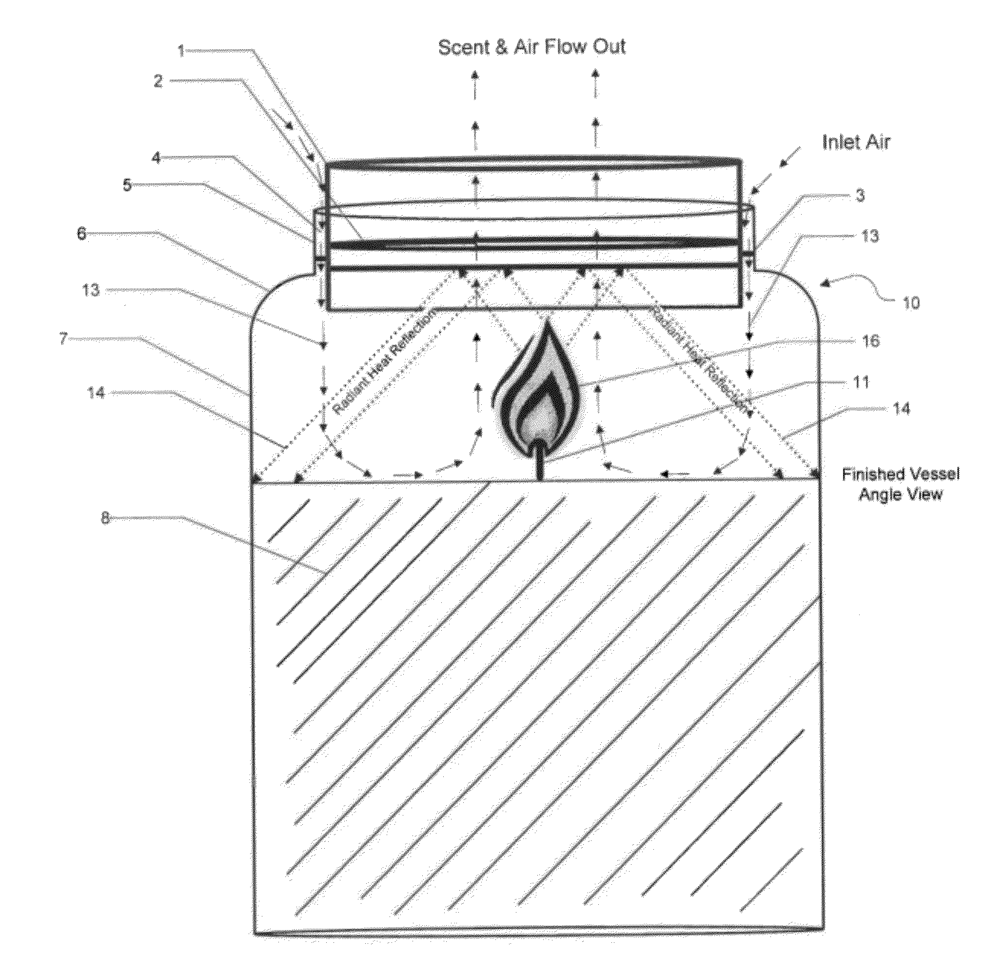
[0009]A candle container design of the present invention enhances performance of the candle during burning by separating the inlet air from the active scent while accelerating the active scent. As part of the container candle manufacturing process a chimney-like assembly is attached to the container creating a finished container candle. In one embodiment the chimney-like assembly is a cylindrical assembly and in another embodiment the chimney-like assembly is a frusto-conical assembly. The chimney-like assembly is a multi-functional part of the container candle that provides two features: 1) separation of inlet air from the active scent released by the container candle, and 2) accelerated delivery of active scent from the container candle. The chimney-like insert part of the assembly improves burn control by stabilizing the candle flame. This function is accomplished by separating inlet air and active scent. In conventional candle containers these two opposing flows interfere with each other causing flame disruption and subsequently inefficient combustion. The chimney-like insert is positioned in a central position on the top of the container with the top extending higher than the brim of the container and the bottom extending some distance into the container's neck. The top and bottom diameters of the chimney-like insert are always more narrow than the container's neck so that an air gap is created between the two. In some embodiments, as part of the container candle manufacturing process, an integrated ring assembly is permanently attached to the container creating a finished container. In other embodiments, the integrated ring is attached to the vessel by one or more contact points during the container candle manufacturing process. In the embodiment utilizing the cylindrical insert, a heat reflection ring is attached inside the air diverter cylinder. The open diameter of the heat reflection ring is adequate for candle lighting. The bottom of the ring may be flat or curved and may or may not contain a reflective surface treatment. The heat reflection ring's function is to reflect thermal radiation back into the candle fuel creating faster and more complete melting. Faster and more complete melting is desired in scented candles as this facilitates the diffusion of fragrance into the atmosphere (known as active scent). The air gap allows for adequate laminar inlet air supply to the candle flame providing for more stable and efficient burning. In the embodiment utilizing the frusto-conical insert, the end of the frusto-conical insert with the larger diameter is positioned in the container's neck to facilitate air flow downward and to the inside wall of the container creating a laminar inlet air flow. The chimney-like insert is attached to a connector ring by three seat flanges positioned 120 degrees apart and the connector ring is attached to the vessel's brim by a u-channel. The advantageous geometry of the frusto-conical insert with the larger diameter of the insert positioned into the vessel's neck creates an accelerated flow of active scent by virtue of the Venturi Effect. Accelerated active scent is desired as this feature propels scent faster and further from the lit candle, thus achieving improved fragrancing performance.

Problems solved by technology

In conventional candle containers these two opposing flows interfere with each other causing flame disruption and subsequently inefficient combustion.

Method used


Image

  • Container Candle with Enhanced Candle Performance and Candle Insert for Container Candle
  • Container Candle with Enhanced Candle Performance and Candle Insert for Container Candle
  • Container Candle with Enhanced Candle Performance and Candle Insert for Container Candle

Examples


Embodiment Construction

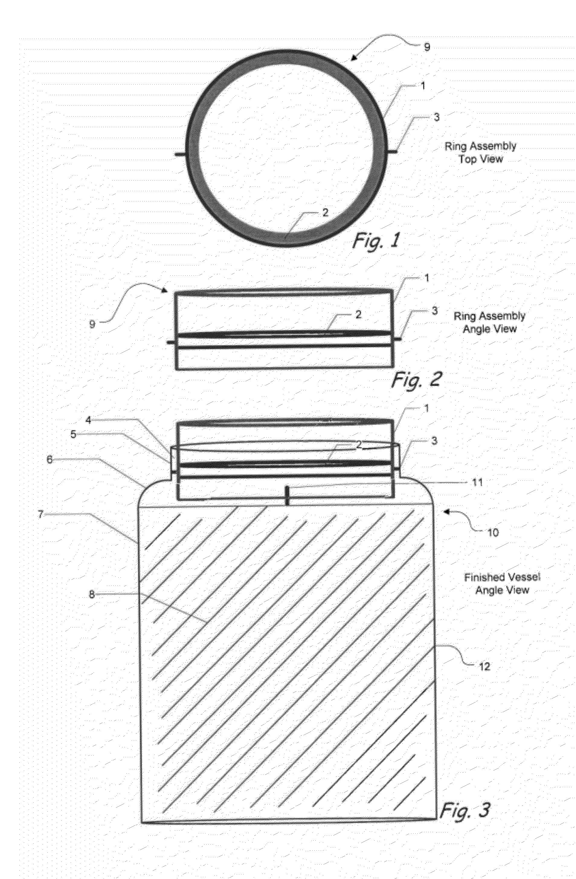
[0018]Referring to the embodiment shown in FIGS. 1-5, a container candle 10 of the present invention includes a container 12, which can be of any shape with an opening at the top of the container. Typically, container 12 would be made of glass, but container 12 could also be made of other non-combustible materials. A chimney-like cylindrical ring assembly 9, shown in FIGS. 1 and 2 is inserted in the container 12. The ring assembly 9 includes an air diverter cylinder 1, a heat reflection ring 2, and contact points 3.

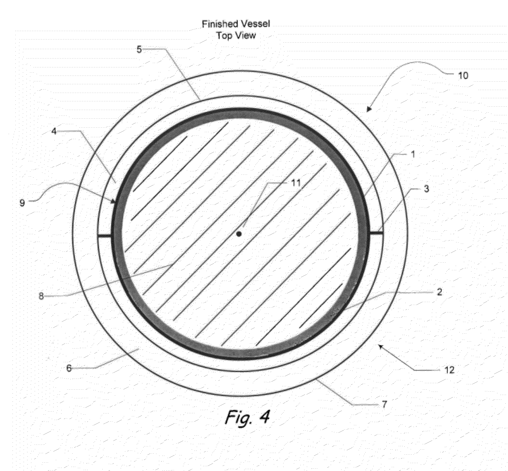
[0019]FIGS. 3 and 4 illustrate a finished container candle 10 with the integrated ring assembly 9 inserted therein. The design of this container candle 10 enhances performance of the candle during burning by controlling the flame and reflecting heat. The ring assembly 9 is connected to the finished container 10 by one or more contact points 3 that are secured to the container by an adhesive. The ring assembly 9 is sized and positioned to allow the formation of an air gap ...


PUM


Abstract

The present invention relates to vessel design that enhances candle performance by separating the inlet air from the active scent while accelerating the active scent. The chimney-like assembly accelerates active scent flow, thus propelling active scent faster and further from the candle. The separation of inlet air from active scent produces an efficient laminar flame with minimal flame movement and flickering, thus reducing the soot potential.

Description

RELATED APPLICATION[0001]This application claims priority to U.S. Provisional Application No. 61 / 442,419, filed on Feb. 14, 2011.BACKGROUND OF THE INVENTION[0002]The present invention relates to candle vessel designs and more particularly to candle vessel designs that enhance the performance of a filled container candle during use.[0003]There are many designs of conventional container-type candles. Many container candles consist of a jar with wax, a wick and a cover. The main function of the containers is to hold wax or some combustible fuel in a static defined dimension. In essence, current container candles function only as a container.[0004]Burn control accessories, however, have been added as a separate component to container candles for the purpose of controlling the flame and for providing improved scent distribution. U.S. Pat. No. 6,382,962 describes a venting plate that is used with apothecary candles to improve combustion efficiency. U.S. Pat. No. 6,589,047 describes the im...

Claims


Application Information

Patent Timeline
Patent Type & Authority Applications(United States)
IPC IPC(8): F23D3/16F23D14/62
CPCF23D3/16F23D3/22A61L9/037F21V37/02C11C5/008F21V35/00C11C5/00
Inventor CAGLE, JOHN E.THOMAS, CHERIYAN B.
Owner YANKEE CANDLE COMPANY
Learn More