
Product, method and system for monitoring physiological function and posture

Active Publication Date: 2012-08-23
MING YOUNG BIOMEDICAL CORP
View PDF34 Cites 121 Cited by
  • Summary
  • Abstract
  • Description
  • Claims
  • Application Information

AI Technical Summary

Benefits of technology

[0015]Preferably, as for the object for detecting physiological function and posture status, wherein the temperature sensor is positioned in materials of different thickness or thermal coefficient. The accuracy of judging posture is increased by means of the difference of heat conduction speed.
[0060]Summarizing the above, the present invention can detect the change in body position accurately; it has significant improvement in terms of technology and renders more positive effects, representing a novel, advanced and practical new design.

Problems solved by technology

In such an “elderly society”, issues of social welfare, medical technology and social security system arise accordingly, and a growing number of elders cannot be taken good care by their families.
As a result; a physiological function detection system is badly in need for them to detect physiological function at any time anywhere to prevent potential accidents.
Unfortunately, a patch electrode is most widely applied today, which may cause to feel uncomfortable on the skin for a long time; and thus is merely suitable for medical treatment on special occasions.
For instance, when a person is changing his / her position frequently during sleeping, it may represent poor sleep quality; when a person is changing his / her position not as frequently as usual during sleeping, it may be thrombus blocking limbs or blood vessel of brain.
U.S. Pat. No. 6,930,608 detects same physiological status using two sensors, but cannot detect the position unrelated to the original sensor.
Thus it can be seen obviously that the aforesaid object for detecting physiological function and posture status has inconvenience and defects with regard to structure and practical use.
However, for a long time, a suitable design has not been developed, and the ordinary products and methods do not posses the appropriate designs that can solve the above problems.

Method used


Image

  • Product, method and system for monitoring physiological function and posture
  • Product, method and system for monitoring physiological function and posture
  • Product, method and system for monitoring physiological function and posture

Examples


embodiment 1

Preferred Embodiment 1

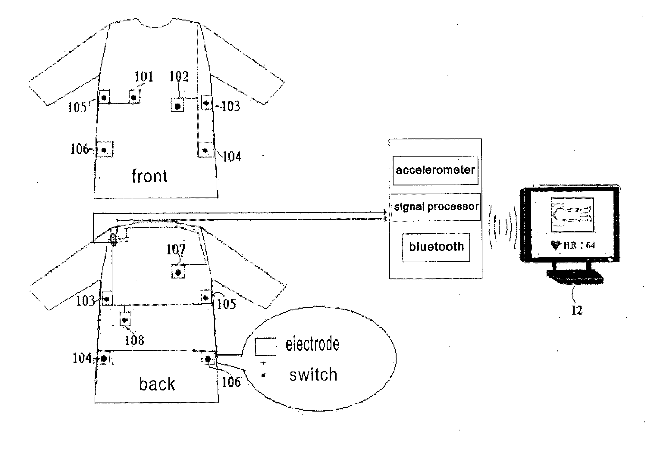
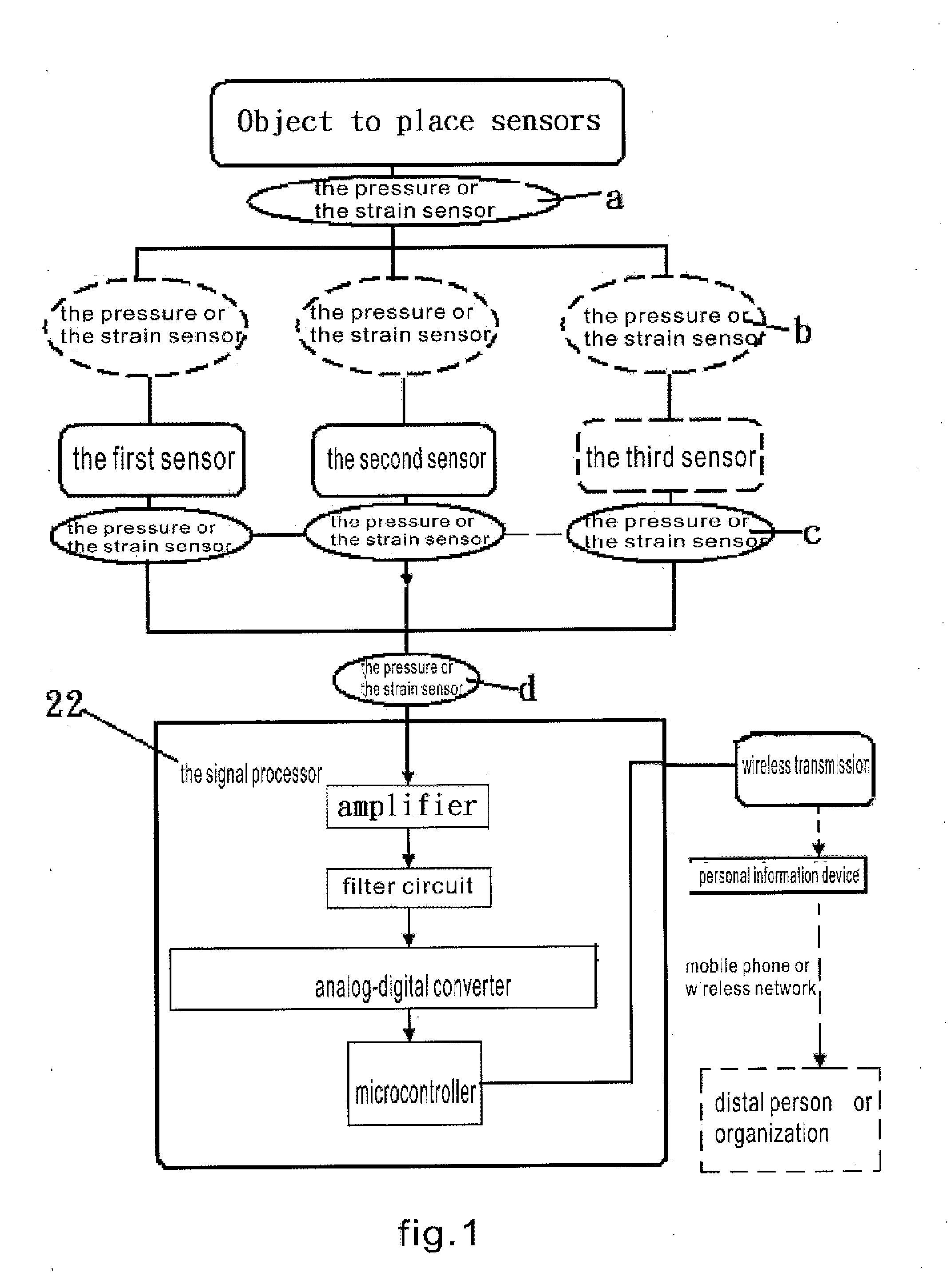
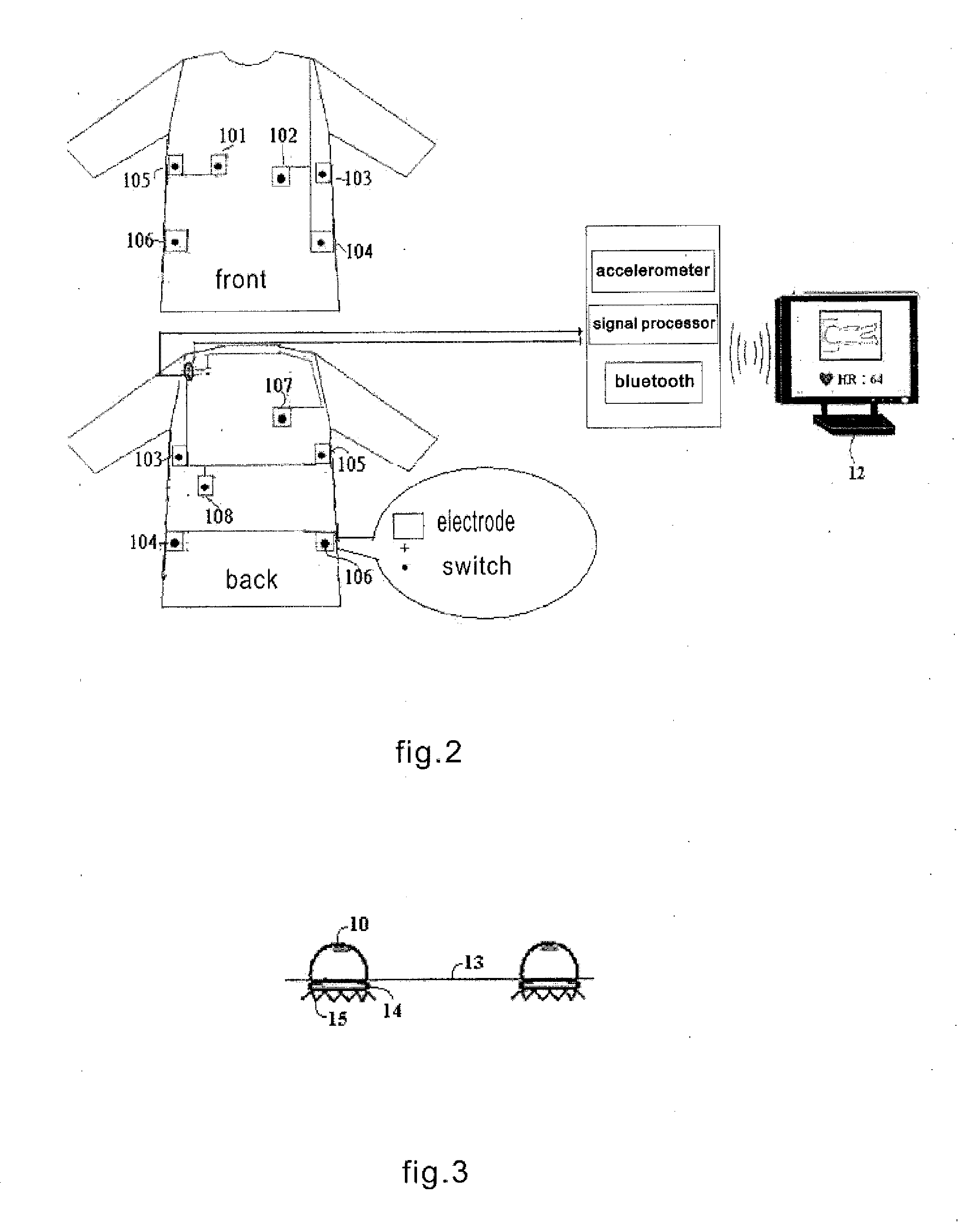
[0095]FIG. 2 and FIG. 3 illustrate separately the block diagram of the first preferred embodiment of the present invention when applied to pajamas, and structure diagram of electrode and key switch of the first preferred embodiment of the present invention. FIG. 2 is used for recording ECG and judging the body position, including electrodes 101, 102, 103, 104, 105, 106, 107 and 108 with key switches, signal processor 22, and PDA or personal computer 12. Structures of the electrodes and key switches are shown in FIG. 3. Electrode 15 that touches body is mounted on specific position on clothes 1; a key switch 10 is deployed above every electrode 15 connected with switch 10 in series. Once key switch 10 is pressed, it gets through and the physiological signal is connected to signal processor 22 which will amplify the analog physiological signal, filter to remove noise and perform analog-to-digital conversion before the ECG waveform is analyzed through the program;...

embodiment 2

Preferred Embodiment 2

[0119]FIG. 9a illustrates the electrode position and connection diagram of the second preferred embodiment of the present invention when applied to a bicycle rider's coat and trousers. The section of circuits may be referred to embodiment 1; wherein electrodes 1-5 are connected in series to a key switch or pressure sensor separately.

[0120]FIG. 9b illustrates the switch, pressure or strain at the gloves. Both right and left hands are with conductive cloth which are made of elastic materials and coupled with a switch, pressure sensor or tension sensor. When walking or sitting, the CEG signals for right and left hands will be sent to the processor to form bipolar ECG. Additionally, a three electrode ECG will be obtained if there is conductive cloth on the hem near the ass, which directly touches the ass, or if some conductive material on underpants touches with the pressure sensor or switch on the hem. The three electrode ECG gives lead two ECG.

[0121]If in summer,...

embodiment 3

Preferred Embodiment 3

[0125]FIG. 11a illustrates the electrode position and connection diagram of the third preferred embodiment of the present invention when applied to a bed. The side view of the electrode is shown in FIG. 11b, wherein the key switch is also an electrode. When a key switch is pressed by human body, the resilient middle layer 1112 of the key switch is compressed so that the upper conductor 1111 contacts the lower conductor 112 and hence the ECG signal is capacitive coupled to 1111 than transmitted to 112 and connected to the input terminal of the amplifier. In preferred embodiment 3 of the present invention, electrodes 12a-12e touching the body are configured on specific positions on the bed, while a key switch or pressure sensor is provided; the section of circuits may refer to FIG. 1; the key switch or pressure sensor is provided on the clothes, as an electrode.

[0126]Electrode 12a and electrode 12b are connected to electrode 12d; electrode 12c and electrode 12e a...


PUM


Abstract

An article for detecting physiological function and posture status is disclosed. The article touches body directly or indirectly; wherein at least a group of non-posture physiological sensors are configured on this object and at least a switch, tension sensor, pressure sensor or pressure applicator are coupled with or touch this object; the switch, tension sensor, pressure sensor or pressure applicator are configured on a different or the same object with the physiological sensors, or divided into two parts that contact each other while external force applied; the non-posture physiological sensors sense the physiological function and posture status of the user.

Description

CROSS REFERENCES TO RELATED APPLICATIONS[0001]This is a continuation-in-part application of PCT / CN2010 / 001252, filed on Aug. 18, 2010, which claims priority to PCT / CN2009 / 000947 filed on Aug. 18, 2009. The disclosures of these prior applications are incorporated by references in their entireties.TECHNICAL FIELD[0002]This disclosure relates to an object, a method and a system for detecting physiological function and posture status, which may be applied to areas such as physical training, medicine, fitness, health care, entertainment, industry security. In particular, it enables to learn the posture status of a user by sensing non-posture physiological signal and can be used to detect changes in terms of working safety, health condition, fitness results and posture status of a user.BACKGROUND OF THE INVENTION[0003]With the rapid improvement of living standard and health care, the human life expectancy is prolonging and proportion of aging population continues to increase. In such an “...

Claims


Application Information

Patent Timeline
IPC IPC(8): A61B5/00A61B5/01A61B5/02A61B7/00A61B5/0478A61B5/0492A61B5/021A61B5/0408A61B5/1455A61B5/296
CPCA61B5/0205A61B5/02055A61B5/1116A61B5/1126A61B5/6805A61B2562/029A61B5/6885A61B5/04085A61B2562/0219A61B2562/0271A61B5/6891A61B5/282
Inventor YANG, CHANG-MINGYANG, TZU-LINYANG, HAO
Owner MING YOUNG BIOMEDICAL CORP
Learn More