Semiconductor device providing a current control function and a self shut down function

a technology of current control and self-shutdown, which is applied in the direction of programme-control, machines/engines, instruments, etc., can solve the problems of engine damage and ignition plug erroneous ignition

Inactive Publication Date: 2012-08-23
FUJI ELECTRIC CO LTD
View PDF5 Cites 16 Cited by
  • Summary
  • Abstract
  • Description
  • Claims
  • Application Information

AI Technical Summary

Benefits of technology

[0034]In embodiments of the semiconductor device providing a current control function and a self shut down function as described above, the pulse generation circuit can include an integration circuit and an inverter that receive a self shut down signal informing detection of the one of abnormal states by the self shut down circuit at an terminal of the integration circuit and at a driving voltage terminal of the inverter, and an output from the integration circuit is delivered to the inverter to generate a pulse signal for a short period of time.
[0035]Ignition semiconductor devices providing a current control function and a self shut down function according to embodiments of the invention can include a pulse generation circuit and a switching circuit wherein the switching circuit is short-circuited for a short period of time immediately after delivery of a self shut down signal Vsd and opened at the time the condition of the reference voltage Vref=the sense voltage Vsns is established. Therefore, an ignition semiconductor device has been provided that performs self shut down operation in a predetermined definite time irrespective of variation in the driving voltage Vb or the load resistance RL. The ignition semiconductor device of certain embodiments also avoids erroneous ignition of the ignition coil in execution of the current control function and the self shut down function.

Problems solved by technology

The rapid shut down of the current Ic utilizing the current control function and the self shunt down function generates oscillation in the current Ic, which would cause erroneous ignition of the ignition plug and damages in the engine.
However, a delay time t6−t5 elapses from delivery of the self shut down signal Vsd until the current Ic starts to decrease.

Method used


Image

  • Semiconductor device providing a current control function and a self shut down function
  • Semiconductor device providing a current control function and a self shut down function
  • Semiconductor device providing a current control function and a self shut down function

Examples


Embodiment Construction

[0045]A semiconductor device providing a current control function and a self shut down function of an embodiment according to the present invention is described in the following with reference to the accompanying drawings.

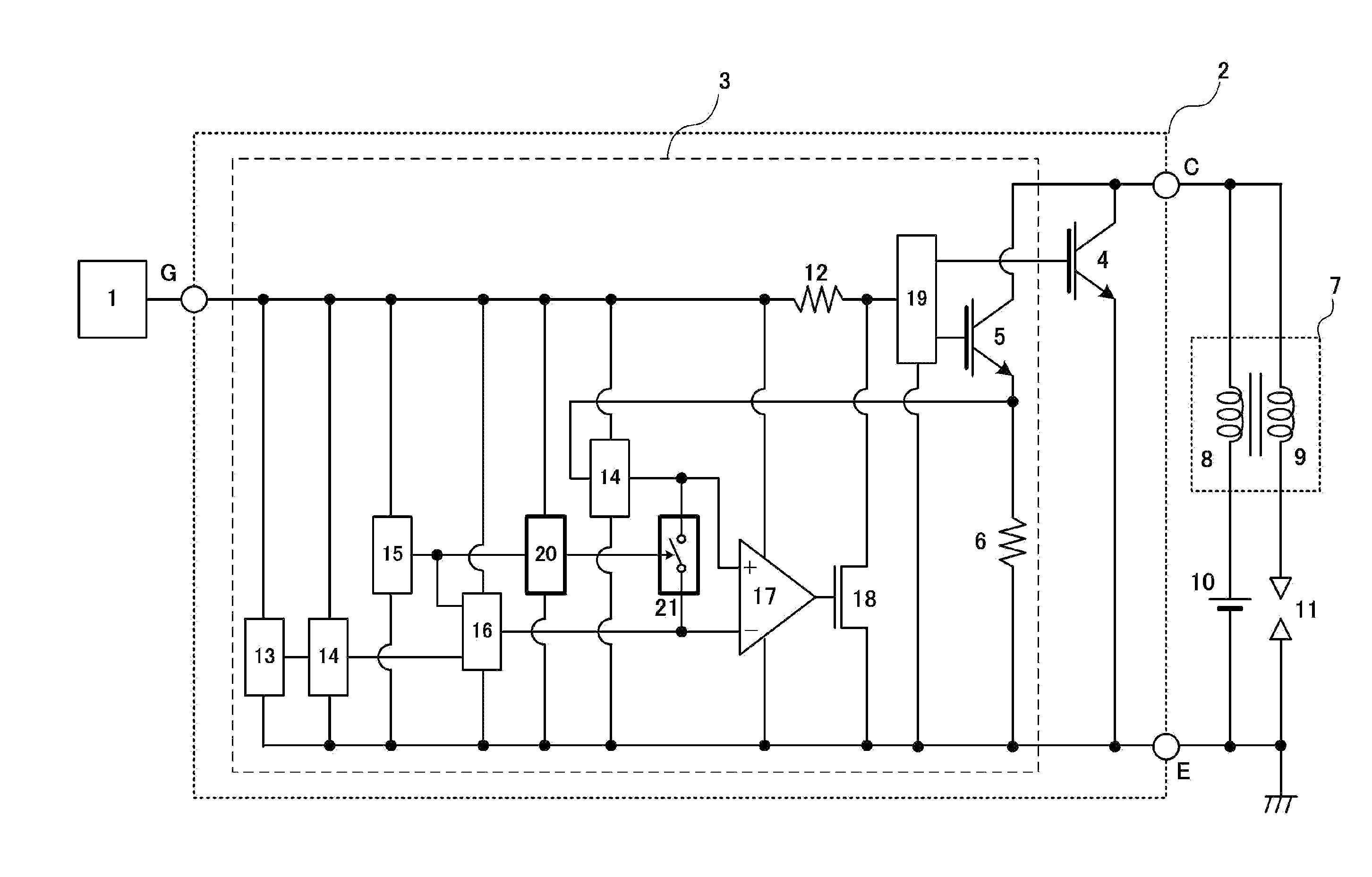
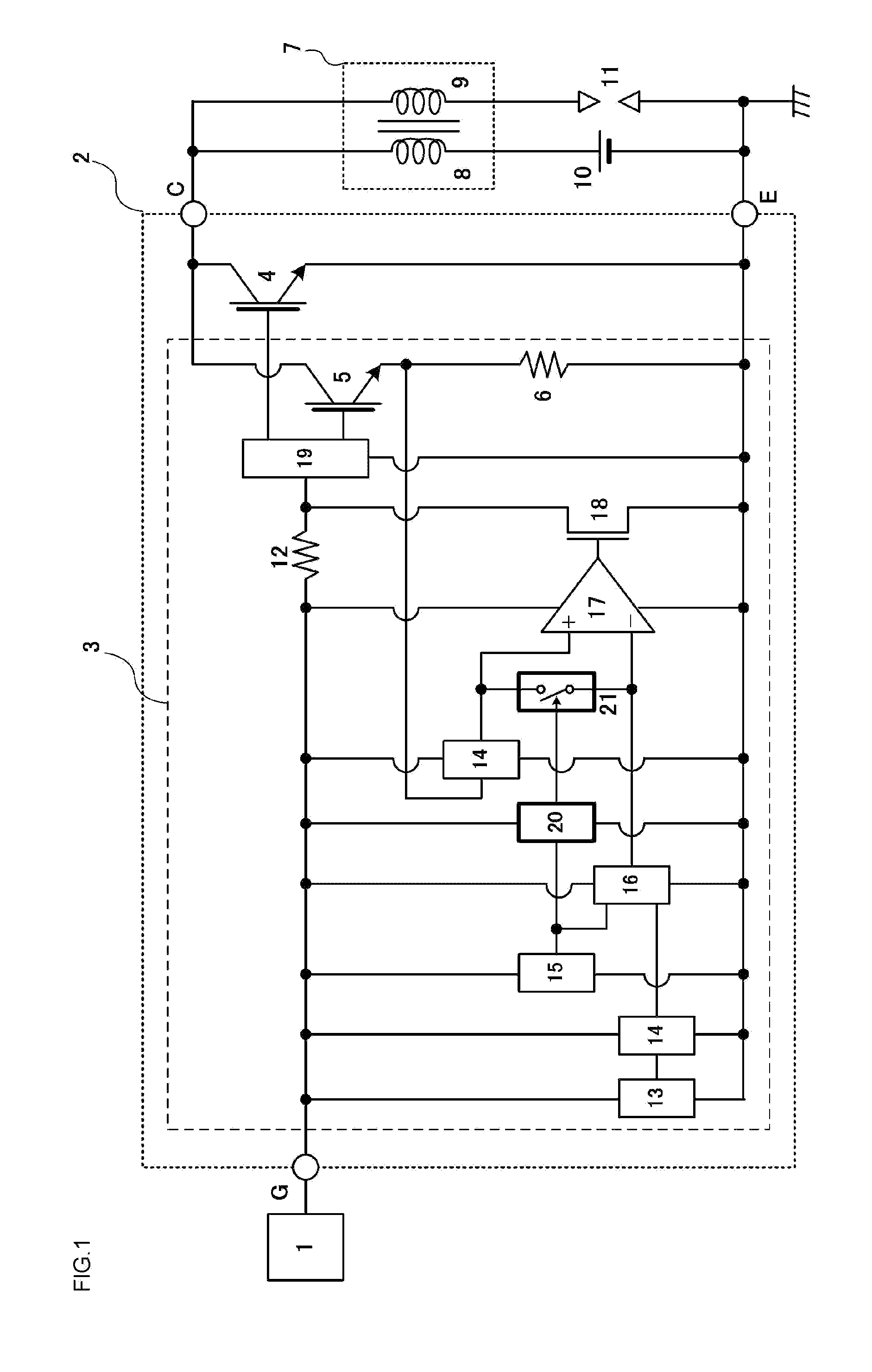
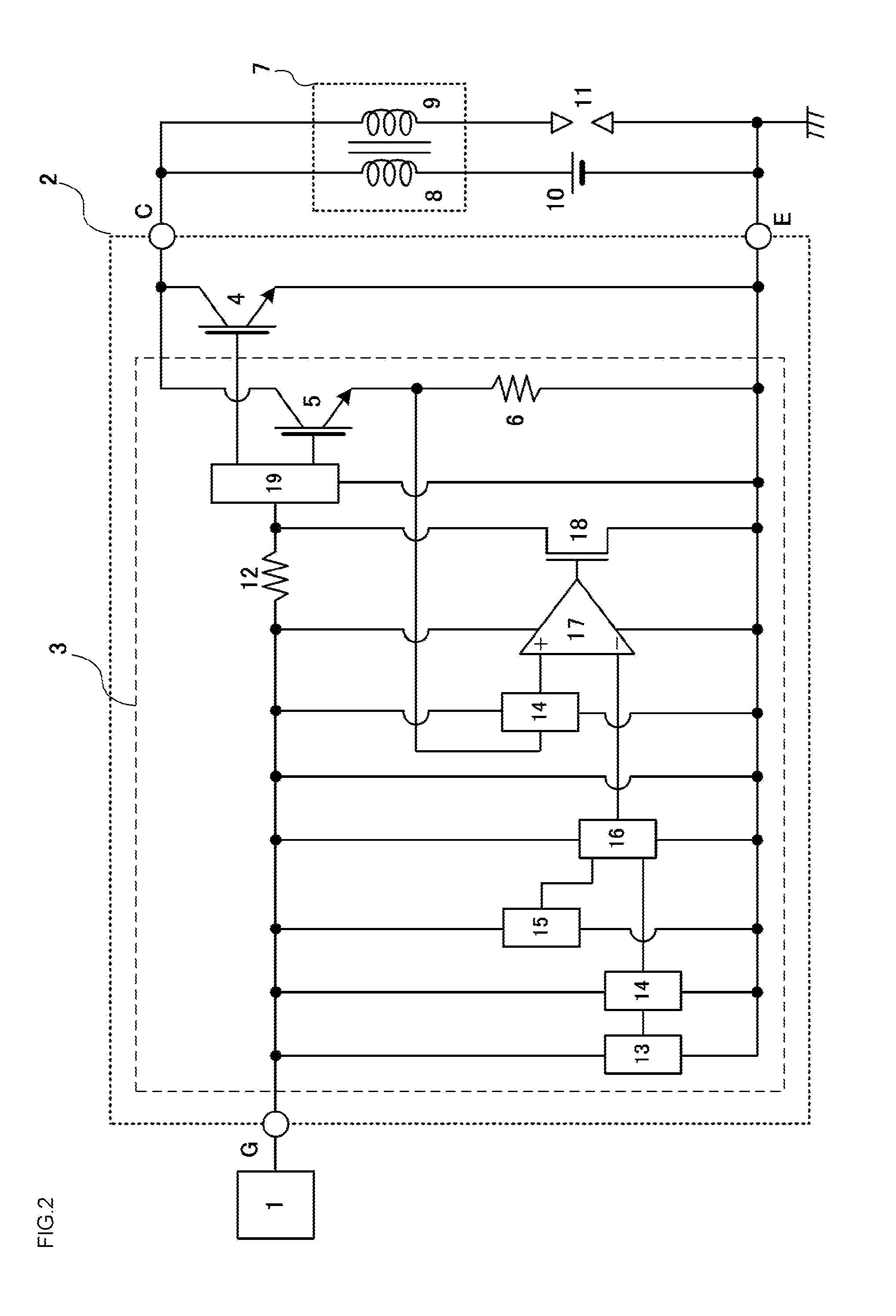
[0046]FIG. 1 shows an example of construction of an ignition semiconductor device providing a current control function and a self shut down function of an embodiment according to the present invention. The same symbols are given to the parts similar to those in the construction example of the conventional ignition semiconductor device shown in FIG. 2 and detailed description thereon is omitted.

[0047]The ignition semiconductor device shown in FIG. 1 comprises an ECU 1, an ignition IC 2, an ignition coil 7, a voltage source 10, and an ignition plug 11.

[0048]The ignition IC 2 comprises an output IGBT 4 (or “ON-OFF unit”) for controlling ON-OFF of the primary current, a current in the primary winding, of the ignition coil 7 and a current control circuit 3 for controlli...


PUM


Abstract

Aspects of the invention are directed to an ignition semiconductor device that includes an output IGBT for ON-OFF control of a primary current in an ignition coil and a current control circuit for controlling a magnitude of the primary current in the ignition coil, the current control circuit being operated by the voltage between the gate terminal and the emitter terminal. The current control circuit can include a sense IGBT, a sense resistance, a gate resistance, a reference voltage, level shift circuits, a self shut down signal generator, a self shut down circuit, an operational amplifier, a MOSFET, a gate voltage control circuit , a pulse generation circuit, and a switching circuit. The self shut down signal generator, on detecting an abnormal state, can deliver a self shut down signal and the pulse generation circuit can generate a pulse signal to short-circuit the switching circuit.

Description

BACKGROUND OF THE INVENTION[0001]1. Field of the Invention[0002]Embodiments of the invention are directed to semiconductor devices, and, in particular, semiconductor devices providing current control and self shut down functions.[0003]2. Description of the Related Art[0004]Ignition devices for internal combustion engines of vehicles use a semiconductor device installing a power semiconductor element to control switching of the primary side current in the ignition coil. FIG. 2 shows a conventional construction example of an ignition semiconductor device for an internal combustion engine of a vehicle using an insulated gate bipolar transistor (in the following, an IGBT) as the power semiconductor element. The construction example of ignition device shown in FIG. 2 is similar to that of Applicants' Japanese Patent Application No. 2010-178317.[0005]The ignition semiconductor device of FIG. 2 comprises an electronic control unit (ECU) 1 for engine control, an ignition semiconductor integ...

Claims


Application Information

Patent Timeline
Patent Type & Authority Applications(United States)
IPC IPC(8): F02D28/00
CPCF02P3/0552
Inventor MIYAZAWA, SHIGEMI
Owner FUJI ELECTRIC CO LTD
Why Eureka
Try Eureka