Stirling engine solar concentrator system

a solar concentrator and stirling engine technology, applied in the direction of machines/engines, mechanical equipment, lighting and heating apparatus, etc., can solve the problems of difficult competition for this technology with other concentrated solar power technologies, and achieve the effects of reducing the cost of the dish structure and associated tracking motor, reducing the cost of the stirling engine, and being robust and inexpensiv

Inactive Publication Date: 2012-08-30
RICOR SOLAR +1
View PDF8 Cites 7 Cited by
  • Summary
  • Abstract
  • Description
  • Claims
  • Application Information

AI Technical Summary

Benefits of technology

[0005]The present invention seeks to provide an improved Stirling dish technology based on a Stirling engine with solar tracker, which by employing a secondary reflector at the primary focal point would allow the Stirling engine to be placed in the base of the parabolic dish rather than on a supporting arm in the center of the primary reflector focal point. This proposed location and re-orientation of the engine has a number of advantages; it relocates the center of gravity of the dish structure leading to a reduction in the cost of the dish structure and associated tracking motor, and also makes the maintenance o

Problems solved by technology

These multiple sub-components, each with their own elements of cost and reliability have made

Method used


Image

  • Stirling engine solar concentrator system
  • Stirling engine solar concentrator system
  • Stirling engine solar concentrator system

Examples


Embodiment Construction

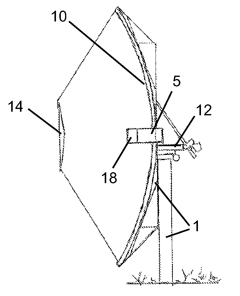
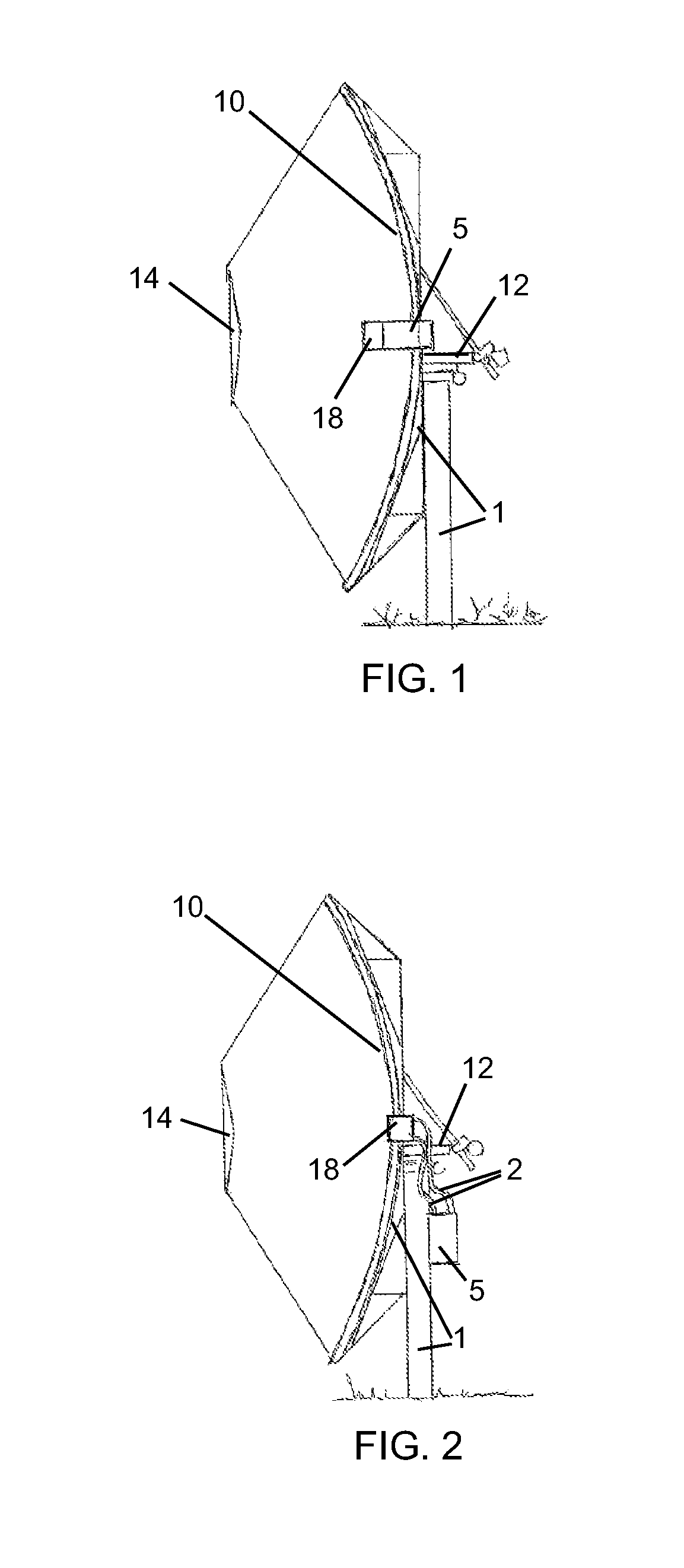
[0028]Reference is now made to FIG. 1 and FIG. 2, which illustrate a system with a Stirling engine (5) with solar tracker (12), a primary reflector (10), a secondary reflector (14), and a receiver (18) mounted on a supporting structure (1), constructed and operative in accordance with two non-limiting embodiments of the present invention.

[0029]The system includes a primary reflector (mirror or reflective film) (10) that is directed to the sun. The solar tracker (12) moves the system to keep the primary reflector (10) at an optimum position, facing the sun from sunrise to sunset. The sunrays are reflected from the primary reflector (10) to a secondary reflector (14) located at the focus of the primary reflector (10).

[0030]The rays are reflected back from the secondary reflector (14) to the receiver (18), located at the focus of the secondary reflector (14). The Stirling engine (5) may be located in close proximity to the receiver (18).

[0031]Regarding the location of the Stirling engi...


PUM


Abstract

A Stirling engine solar concentrator system including a primary reflector (10) mounted on a base supporting structure (1), a secondary reflector (14) located at a focus of the primary reflector (10). a receiver (18) located at a focus of the secondary reflector (14), wherein sunrays are reflected from the primary reflector (10) to the secondary reflector (14) and are reflected back from the secondary reflector (14) to the receiver (18), and a Stirling engine (5) located near the receiver (18), characterised by a cooling system of the Stirling engine (5) including a plurality of heat transfer elements (6, 8) mounted on a shaded side of the primary reflector (10), wherein a cooling fluid (19) is arranged to flow between the Stirling engine (5) and the heat transfer elements (6, 8).

Description

FIELD OF THE INVENTION[0001]The present invention relates generally to Stirling dishes solar technology.BACKGROUND OF THE INVENTION[0002]Stirling engines have very high efficiencies in their conversion of thermal heat to work. Their ability to be powered by a variety of fuel sources and at high temperatures in excess of 700° C. has made them ideal power converting units for concentrated solar energy. In light of this potential, Stirling-dish solar power converters have been developed in which a reflective parabolic dish structure focuses incoming Direct Normal Irradiation (DNI) on the Stirling engine heat intake port (receiver) which is located in the center of the dish's primary focal point. This same Stirling engine transforms the incoming thermal heat into electricity by means of the Stirling thermal mechanical cycle. Primarily there exist two main genres of Stirling engines; the classical design is the kinematic engine which is based on a rotating shaft with a phase-linking rod ...

Claims


Application Information

Patent Timeline
IPC IPC(8): F03G6/04F02G1/055F03G6/06F24S20/20F24S10/95F24S23/71F24S23/79
CPCF02G1/055F02G2254/30F02G2256/02F02G2256/04F24J2/07Y02E10/46F24J2/18F24J2/30Y02E10/41Y02E10/42Y02E10/44F24J2/12F24S10/30F24S20/20F24S23/71F24S23/79F03G6/068Y02E10/40
Inventor GARAWAY, ISAACHAREL, EREZSOSA NARANJO, CRISTINAMUNOZ GILABERT, FELIX
Owner RICOR SOLAR
Why Eureka
Try Eureka