
Test device and test method for measuring a phase noise of a test signal

a phase noise and test signal technology, applied in the field of phase noise measurement, can solve the problems of difficult automation of methods, frequent and time-consuming calibrations, and performance degradation of communication systems, and achieve the effects of simple structure, good phase noise properties, and simplified calibration process

Active Publication Date: 2012-08-30
ADVANTEST CORP
View PDF5 Cites 20 Cited by
  • Summary
  • Abstract
  • Description
  • Claims
  • Application Information

AI Technical Summary

Benefits of technology

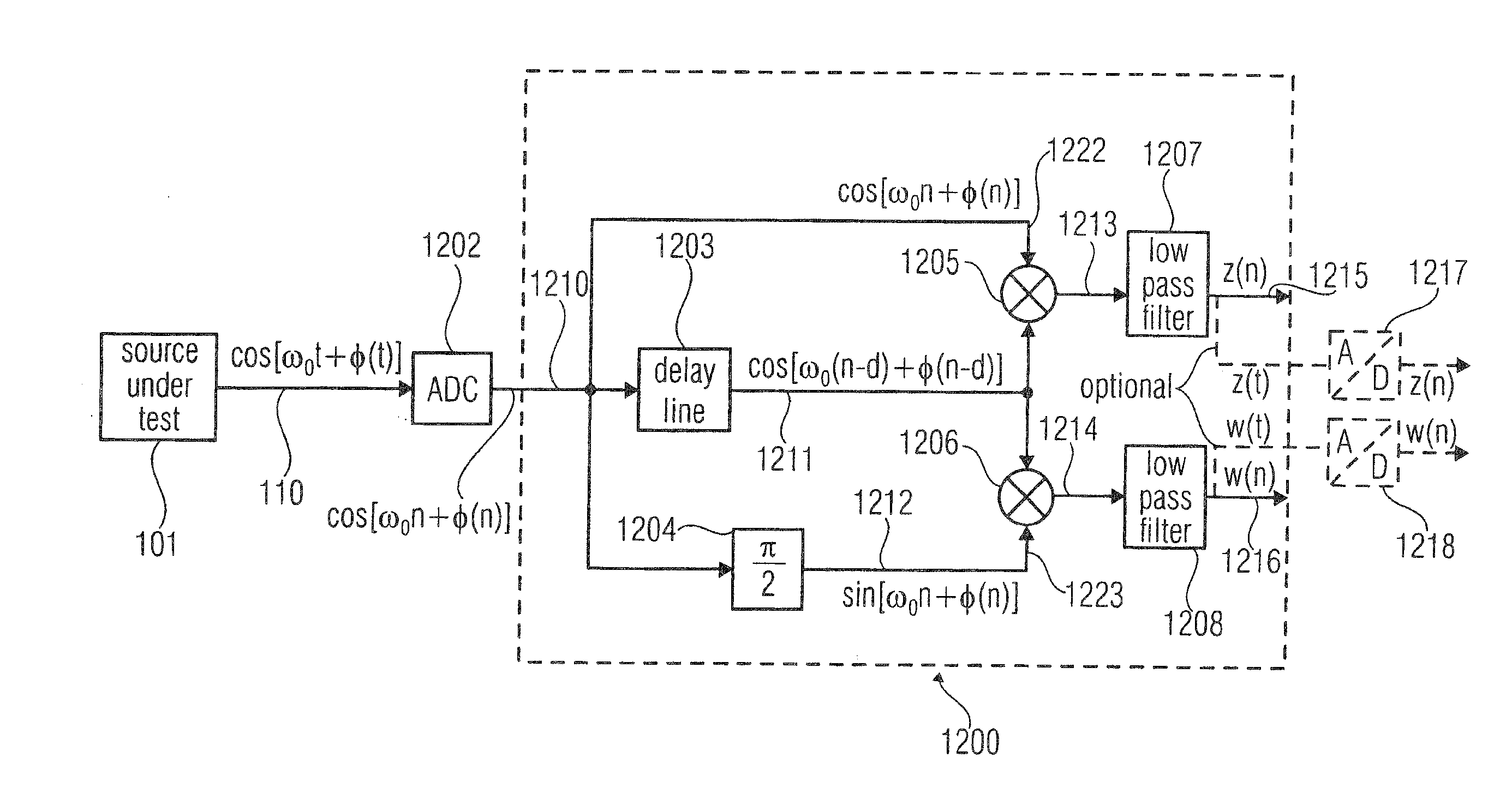
[0011]Embodiments of the present invention may utilize two mixers instead of only one mixer as used in a conventional delay-line discriminator. As result, input signals of the mixers do not need to be in quadrature. Accordingly, the calibration process is simplified in some embodiments of the invention. In one embodiment the first signal, which is input to the first mixer, and the second signal, which is input to the second mixer, are phase-shifted with respect to each other. In some embodiments of the invention, the first signal and the second signal are in phase quadrature with respect to each other. Embodiments of the invention, which make use of a phase quadrature of the first signal and the second signal, provide a noise power of the phase noise of the test signal which is independent of the frequency of the test signal.
[0012]Embodiments of the invention provide a test device and a test method for measuring a phase noise of a test signal, which have a simpler architecture and retain the advantages of the delay-line discriminator without the need of complex calibrations. Embodiments of the invention provide a cost-efficient device and method for phase noise measurements. Complex calibrations are not required, such that an automatic testing, e.g. by automatic test equipment (ATE), is facilitated. Using embodiments of the invention, external sources with good phase noise properties are also not necessary. In addition, expensive tunable phase shifters are not required, as the input signals to the mixer do not necessarily have to be in phase quadrature. Some embodiments of the invention comprise a phase shifter that does not have to be tunable. The phase shifter may have a fixed phase, which may be fixed for each input frequency (or independent of the input frequency), such that no calibration process is required for adjusting a phase. A phase noise measurement may be performed time-efficiently and is well adapted for automated measurements.

Problems solved by technology

Phase noise of signal sources may be a severe cause of performance degradation in communication systems.
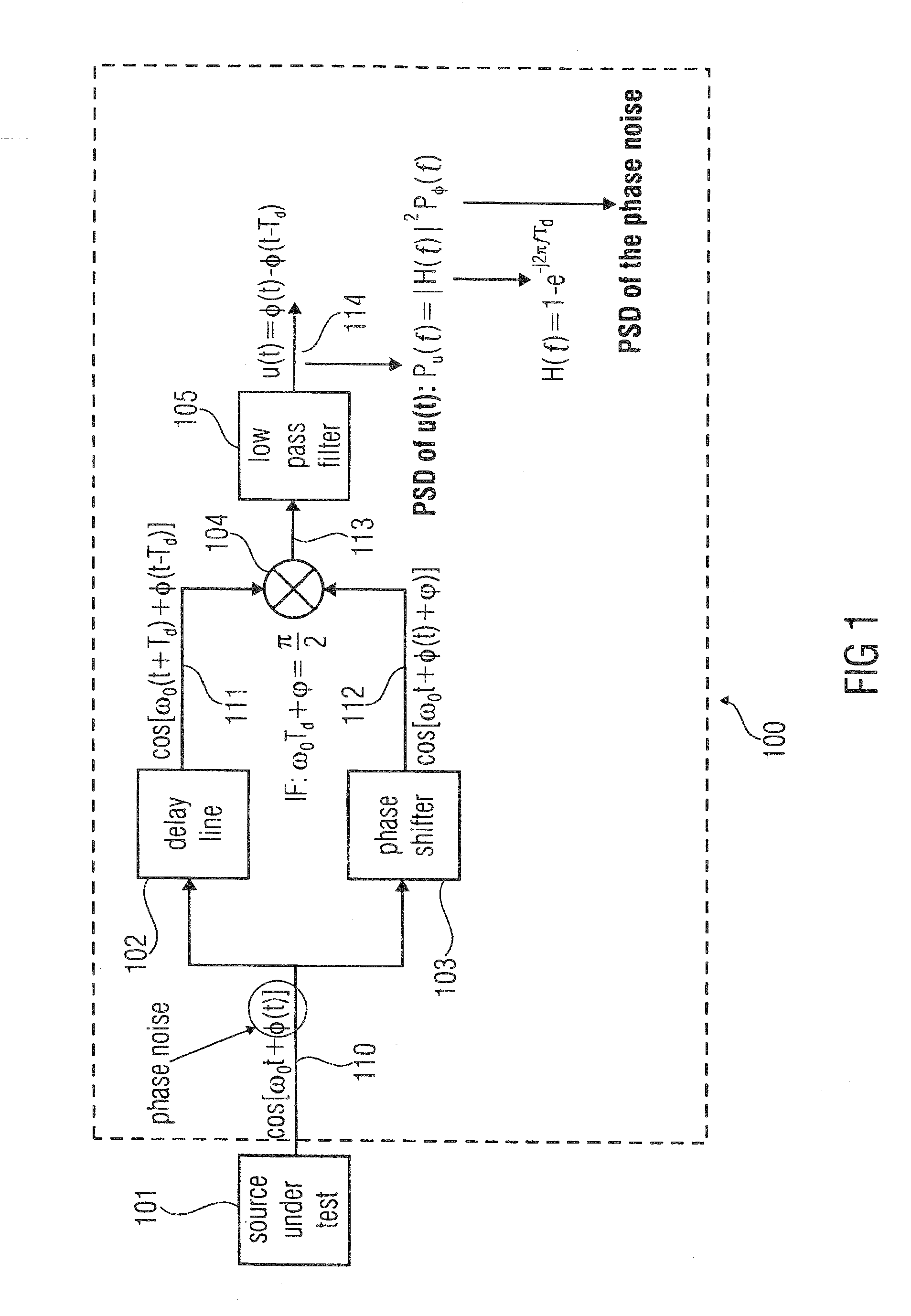
However, for tuning the tunable phase shifter, frequent and time-consuming calibrations may be necessitated.
Furthermore, such a method may be difficult to automate.
The tunable phase shifter 103 has to be adjusted for each input frequency, making the calibration process time consuming and not well indicated for automatic measurements.

Method used


Image

  • Test device and test method for measuring a phase noise of a test signal
  • Test device and test method for measuring a phase noise of a test signal
  • Test device and test method for measuring a phase noise of a test signal

Examples


Embodiment Construction

[0028]Reference will now be made in detail to the preferred embodiments of the present invention, examples of which are illustrated in the accompanying drawings. While the invention will be described in conjunction with the preferred embodiments, it will be understood that they are not intended to limit the invention to these embodiments. On the contrary, the invention is intended to cover alternatives, modifications and equivalents, which may be included within the spirit and scope of the invention as defined by the appended claims. Furthermore, in the following detailed description of embodiments of the present invention, numerous specific details are set forth in order to provide a thorough understanding of the present invention. However, it will be recognized by one of ordinary skill in the art that the present invention may be practiced without these specific details. In other instances, well-known methods, procedures, components, and circuits have not been described in detail ...


PUM


Abstract

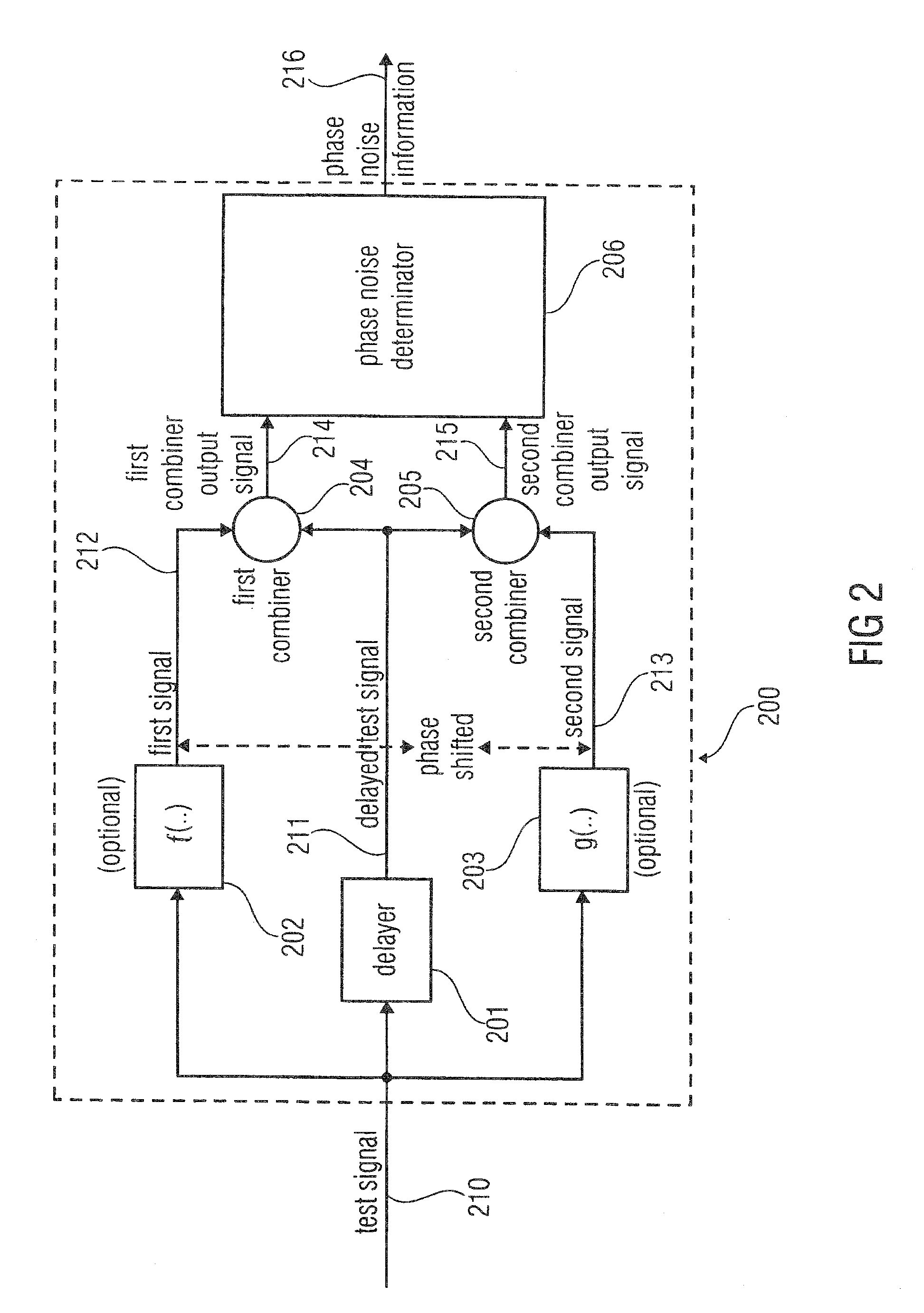
A test device for measuring a phase noise of a test signal includes a delayer configured to delay the test signal to provide a delayed test signal, a first combiner, a second combiner, and a phase noise determinator. The first combiner is configured to combine a first signal with the delayed test signal to provide a first combiner output signal. The first signal is based on the test signal or a signal identical to the test signal. The second combiner is configured to combine a second signal with the delayed test signal, wherein the second signal is phase-shifted with respect to the first signal to provide a second combiner output signal. The second signal is based on the test signal. The phase noise determinator is configured to provide phase noise information that depends on the first combiner output signal and the second combiner output signal.

Description

CROSS-REFERENCES TO RELATED APPLICATIONS[0001]This application is a Continuation of and claims priority to International Application No. PCT / EP2009 / 007546, filed on Oct. 21, 2009, titled “TEST DEVICE AND TEST METHOD FOR MEASURING A PHASE NOISE OF A TEST SIGNAL,” by Pausini, et al., which is herein incorporated by reference.TECHNICAL FIELD[0002]The present disclosure relates generally to the field of test signal analysis and more specifically to the field of phase noise measurement.BACKGROUND[0003]Phase noise of signal sources may be a severe cause of performance degradation in communication systems. Thus, in the production stage of radio frequency (RF) chips that are configured to handle electrical, optical and / or other electro-magnetic signals in the radio frequency range (3 kHz up to 300 THz), it is important to accurately measure any phase noise present in an output signal of the device under test (DUT), while keeping the cost of test (COT) as low as possible.[0004]Exemplary dela...

Claims


Application Information

Patent Timeline
IPC IPC(8): G01R29/26
CPCG01R31/31709G01R29/26
Inventor PAUSINI, MARCO
Owner ADVANTEST CORP
Learn More