Apparatus and methods for optical coherence tomography and confocal microscopy

a technology of optical coherence tomography and confocal microscopy, applied in the field of optical scanning, can solve problems such as signal loss, beam splitter loss, and signal loss

Inactive Publication Date: 2012-08-30
THUNDER BAY REGIONAL RES INST
View PDF8 Cites 9 Cited by
  • Summary
  • Abstract
  • Description
  • Claims
  • Application Information

AI Technical Summary

Benefits of technology

[0010]In an aspect of the present invention, an optical imaging device which receives an optical collimated input beam is provided, the device comprising a beam splitter which splits the input beam into a sample beam and a reference beam, wherein the sample beam is scattered from a substance to generate a return beam; a pair of axicon lenses through which at least one of the sample beam and the return beam is directed to bypass a reflector that redirects at least one of the input beam and the reference beam, to prevent either the return beam or the reference beam from interfering with the input beam; and a detector which detects an interference pattern of an output beam generated by interfering the reference beam with the return beam.

Problems solved by technology

In each of OCT systems and confocal imaging systems, signal losses can occur due to the particular optical components used and their respective arrangement.
For example, beam splitters can introduce losses.
The same beam splitter then can generate an output beam, the output beam being an interference beam generated by interfering the reference beam with the return beam by the same beam splitter reflecting a portion of the return beam and transmitting a portion of the reference beam through the beam splitter; however, losses in the signal occur due to a portion of the return beam being transmitted through the beam splitter, along with a portion of the reference beam being reflected by the beam splitter, these portions being directed back toward the input source.
The beam portions directed back to the input source additionally interfere with the input source, causing signal losses in the output signal.
In such systems the same losses occur, but a desired intensity signal of the output beam intensity can be generated at a cost of additional energy due to the increased intensity of the input signal.

Method used


Image

  • Apparatus and methods for optical coherence tomography and confocal microscopy
  • Apparatus and methods for optical coherence tomography and confocal microscopy
  • Apparatus and methods for optical coherence tomography and confocal microscopy

Examples


Embodiment Construction

[0028]It will be appreciated that for simplicity and clarity of illustration, where considered appropriate, reference numerals may be repeated among the figures to indicate corresponding or analogous elements or steps. In addition, numerous specific details are set forth in order to provide a thorough understanding of the embodiments described herein. However, it will be understood by those of ordinary skill in the art that the embodiments described herein may be practiced without these specific details. In other instances, well-known methods, procedures and components have not been described in detail so as not to obscure the embodiments described herein. Furthermore, this description is not to be considered as limiting the scope of the embodiments described herein in any way, but rather as merely describing the implementation of the various embodiments described herein.

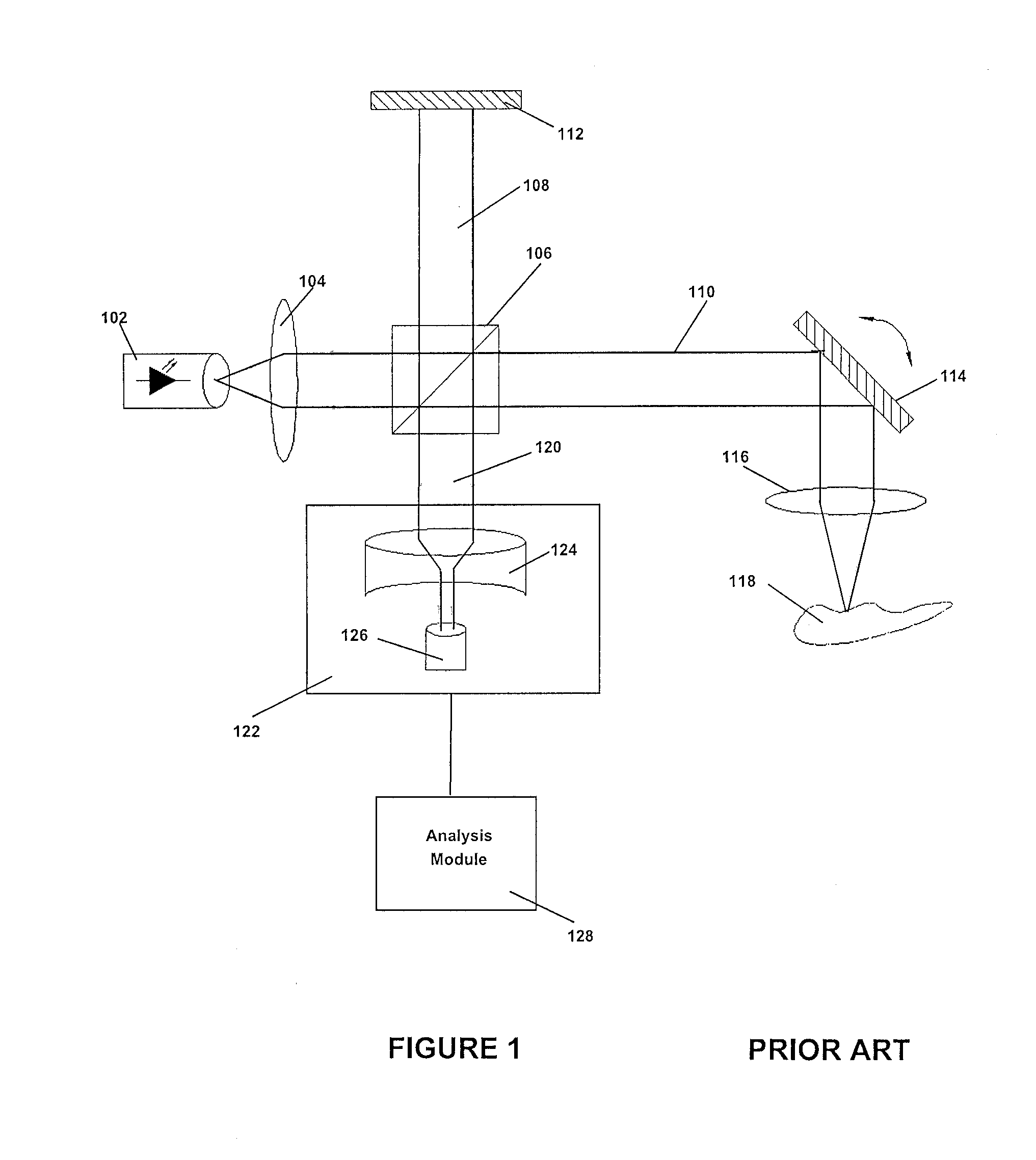
[0029]For the purpose of understanding signal losses in typical OCT systems, FIG. 1 shows an embodiment of OCT sy...


PUM


Abstract

An optical imaging device which receives an optical collimated input beam, the device having a pair of axicon lenses through which a beam is directed to generate a collimated ring beam, wherein the ring beam is scattered from a substance to generate a return beam, and to bypass a reflector that redirects the return beam to prevent the return beam from interfering with the input beam; and a detector which detects an image projected by the return beam.

Description

RELATED APPLICATIONS[0001]This application claims priority from U.S. Provisional Application No. 61 / 247,753 filed Oct. 1, 2009, the contents of which are herein incorporated by reference.FIELD OF INVENTION[0002]This invention relates to the field of optical scanning and more specifically relates to improved apparatus and methods for optical coherence tomography and confocal microscopy.BACKGROUND[0003]An optical source can be a cost-effective way of obtaining certain information from a substance by penetrating the surface, or surfaces, of a substance, and being subsequently scattered or reflected by the surface or surfaces. As described herein, surfaces includes interior surfaces within a substance. This scatter or reflection can be used to provide useful information with respect to the depth profile or physical structure of the surface. For example, certain medical imaging techniques can measure the reflectivity as a function of depth, and use this information to produce a three-dim...

Claims


Application Information

Patent Timeline
Patent Type & Authority Applications(United States)
IPC IPC(8): G01B9/02
CPCA61B5/0066G01N21/4795G01B9/02091G01B9/02056G02B27/283
Inventor CENKO, ANDREW T.MEADE, JEFFREY T.HAJIAN, ARSEN R.KIM, JAE K.
Owner THUNDER BAY REGIONAL RES INST
Why Eureka
Try Eureka