Distributed power supply system and control method thereof
a power supply system and distribution power technology, applied in the direction of electric variable regulation, process and machine control, instruments, etc., can solve the problem that the fuel cell apparatus 104 consumes electric power, and achieve accurate diagnostic results and electric power values.
- Summary
- Abstract
- Description
- Claims
- Application Information
AI Technical Summary
Benefits of technology
Problems solved by technology
Method used
Image
Examples
embodiment 1
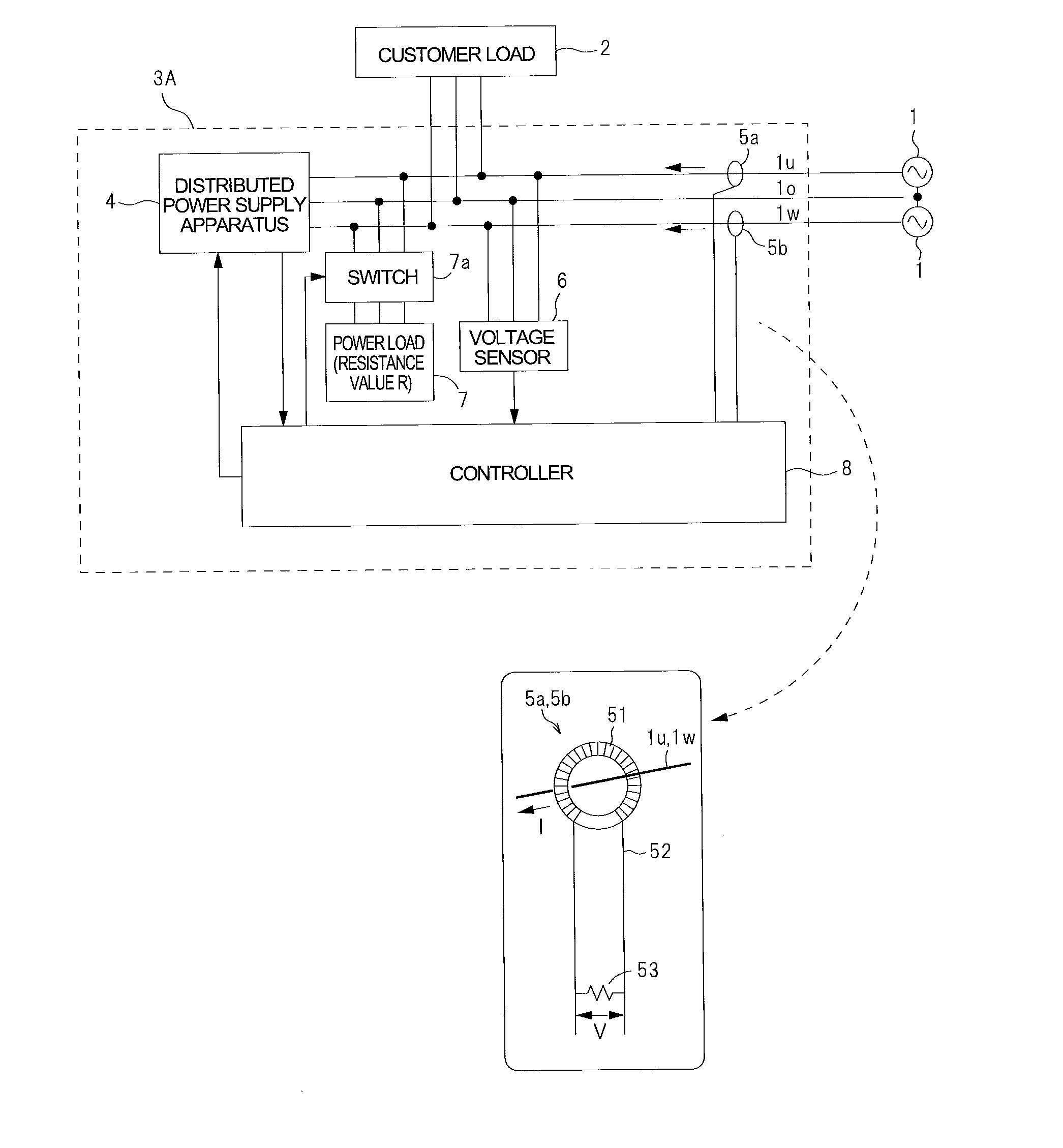
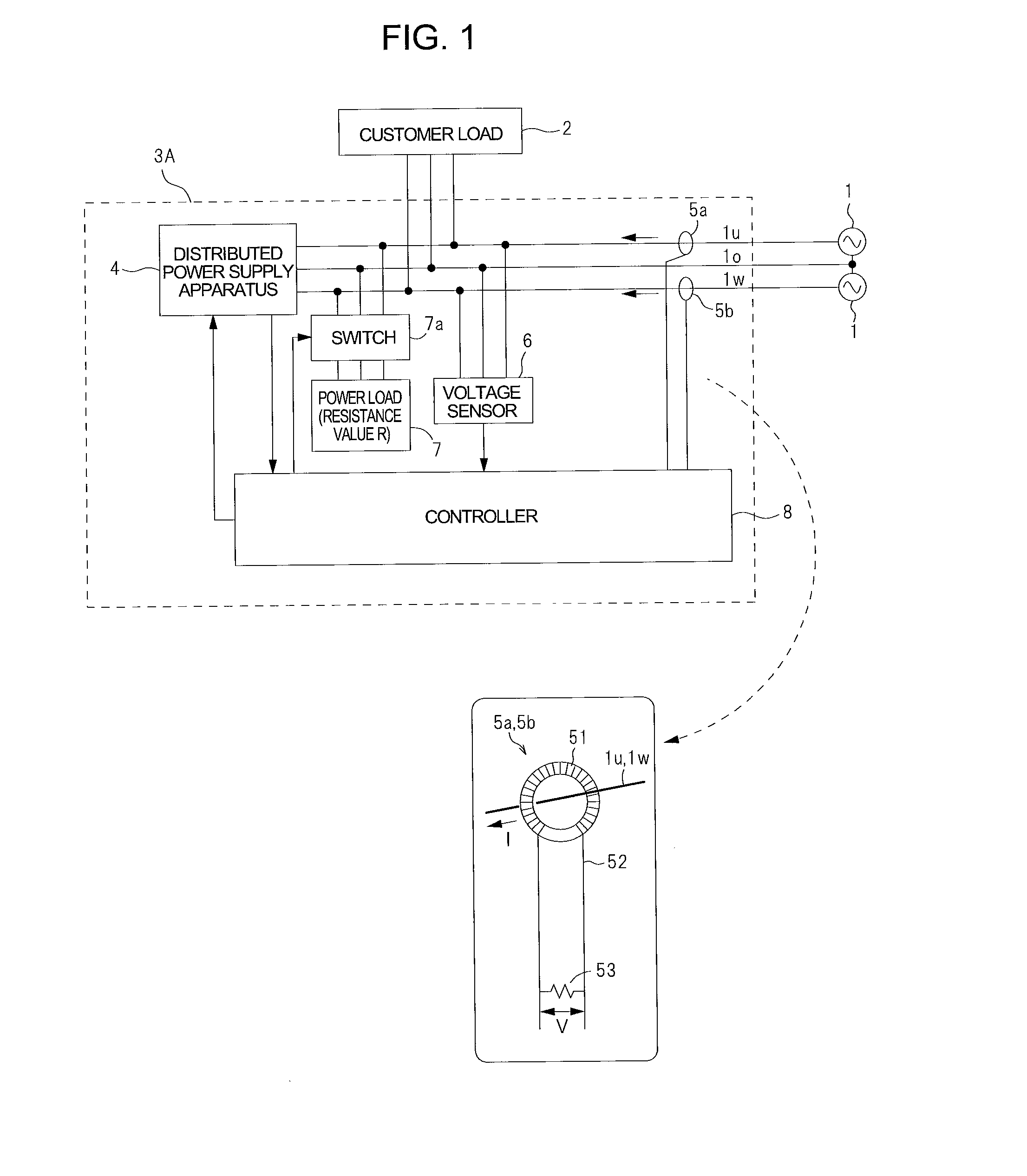
[0049]FIG. 1 is a block diagram showing a configuration of a distributed power supply system according to Embodiment 1 of the present invention. As shown in FIG. 1, a distributed power supply system 3A of the present embodiment is situated between a commercial power utility 1 and a customer load (power demand site) 2. Although in the present embodiment, the commercial power utility 1 is a single-phase three-wire AC power supply composed of U-phase, O-phase and W-phase as the commercial power utility 1, a single-phase two-wire circuit or a two-phase three-wire circuit may be used. The customer load 2 is defined as equipment which consumes electric power, for example, a laundry machine installed at a customer. The customer includes general homes, schools, hospitals, etc.
[0050]The distributed power supply system 3A includes a distributed power supply apparatus 4 which outputs AC power and current sensors 5a, 5b. The distributed power supply apparatus 4 is connected to the commercial po...
embodiment 2
[0078]Next, description will be given of a specific configuration of a distributed power supply system 3B and a specific content of a current sensor diagnostic process executed by the distributed power supply system 3B. FIG. 6 is a block diagram showing a configuration of the distributed power supply system 3B according to Embodiment 2. In the distributed power supply system 3B, the distributed power supply apparatus 4 includes a power generation unit 4a and an inverter 4b. The controller 8 includes a power calculating section 11, a current sensor state determination section 12, a nonvolatile memory 13, a sign inverting section 14 and a power load control section 15.
[0079]The power calculating section 11 calculates a product of a current value from the current sensor 5a(5b) input to the controller 8 and a voltage value from the voltage sensor 6, to derive electric power for each of U-phase and W-phase. The power load control section 15 controls ON / OFF of the switch 7a. The current s...
embodiment 3
[0099]Another specific configuration of a distributed power supply system 3C will be described. FIG. 8 is a block diagram showing a configuration of the distributed power supply system 3C according to Embodiment 3. The distributed power supply system 3C determines whether or not there is an installation problem of the current sensor 5a(5b), disconnection of the winding wire 52, or a failure of current sensor 5a(5b), in the current sensor diagnostic process. As shown in FIG. 8, the distributed power supply system 3C further includes a volatile memory 16, a current sensor abnormality determiner section 17, a switch 18, and a time measuring section 19, which are added to the constituents in the distributed power supply system 3B of Embodiment 2.
[0100]The volatile memory 16 is configured to receive signals from the power calculating section 11 and from the power load control section 15 as inputs. The volatile memory 16 is capable of storing the electric power value calculated by the pow...
PUM
 Abstract
Description
Claims
Application Information
 - R&D
- Intellectual Property
- Life Sciences
- Materials
- Tech Scout
- Unparalleled Data Quality
- Higher Quality Content
- 60% Fewer Hallucinations
Browse by: Latest US Patents, China's latest patents, Technical Efficacy Thesaurus, Application Domain, Technology Topic, Popular Technical Reports.
© 2025 PatSnap. All rights reserved.Legal|Privacy policy|Modern Slavery Act Transparency Statement|Sitemap|About US| Contact US: help@patsnap.com


