Intravenous fluid heater

a technology of fluid heater and fluid flow, which is applied in the field of intravenous fluid heater, can solve the problems of only accurate gauge, no automatic determination of whether such bubbles are present, and poor performance of battery-powered fluid heaters, and achieves the effects of less power, increased total heat transfer, and unparalleled strength and flexibility

Inactive Publication Date: 2012-08-30
NORTH AMERICAN RESCUE PRODS
View PDF4 Cites 6 Cited by
  • Summary
  • Abstract
  • Description
  • Claims
  • Application Information

AI Technical Summary

Benefits of technology

[0017]In one alternate exemplary embodiment, there is disclosed a portable intravenous tube system including a heating apparatus for heating an intravenous fluid including an apparatus for providing energy for use in transferring heat with the intravenous fluid, a housing for receiving at least a portion of the intravenous tube, an energy source for transferring heat to the intravenous fluid flowing in the intravenous tube; and wherein the intravenous tube is coiled for a given length within the housing to increase the total heat transferred to the intravenous fluid flowing through the intravenous tube.
[0018]In one particular exemplary embodiment, there is disclosed an intravenous thermal device that includes a thin-film heater element consisting of a relatively thin polyamide, PTC or polyester film impregnated with a resistive carbon layer onto which conductive busses are printed. The film of the heater element itself is less than 0.5 mm thick with unparalleled strength, flexibi

Problems solved by technology

Battery powered IV fluid warmer have heretofore had poor performance because of the battery sources which have been available.
Further, it is understood that the TA-200 model Thermal Angel® battery has a complete charge time of approximately twelve hours and cannot be fast charged.
In addition, The TA-200 model Thermal Angel® battery has only a simplified gauge which is only accurate when the battery is not in use.
A yet further disadvantage of the heating arrangement disclosed in the '693 patent is that although means are included for reducing gas bubble formation in the infusion fluid, no means are provided for automatically determining whether such bubbles are present in the fluid or whether there has been reduction in fluid flow rate, and for taking appropriate action (e.g., providing warning and/or stopping fluid flow into the patient) in the event such conditions are determined to be present.
As will be appreciated by those skilled in the art, if left

Method used


Image

  • Intravenous fluid heater
  • Intravenous fluid heater
  • Intravenous fluid heater

Examples


Embodiment Construction

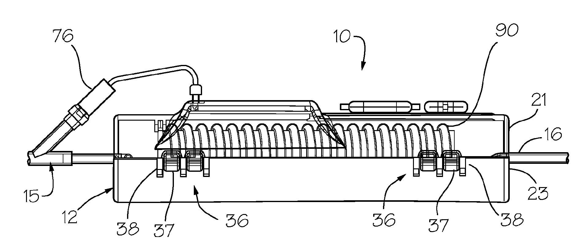
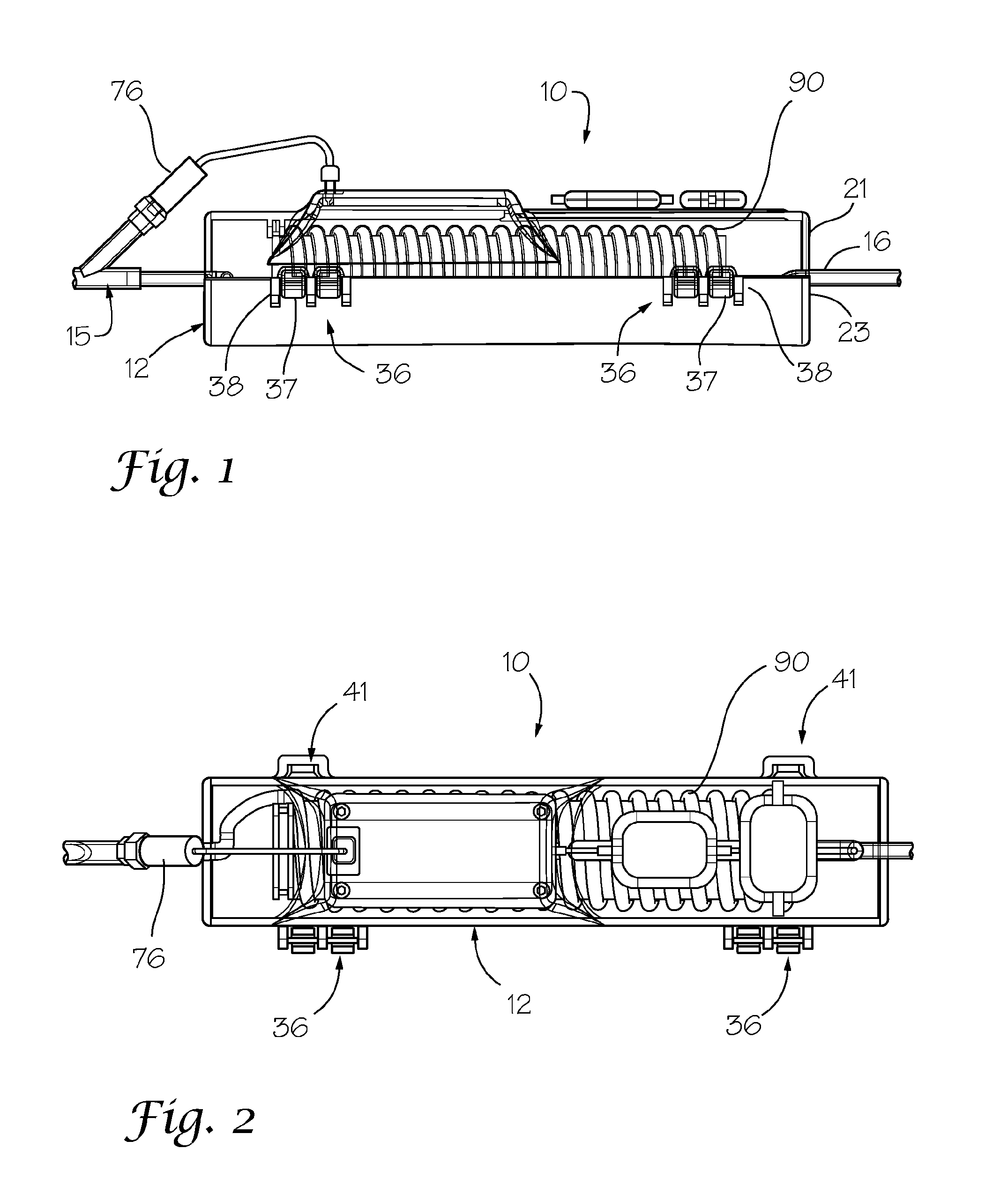
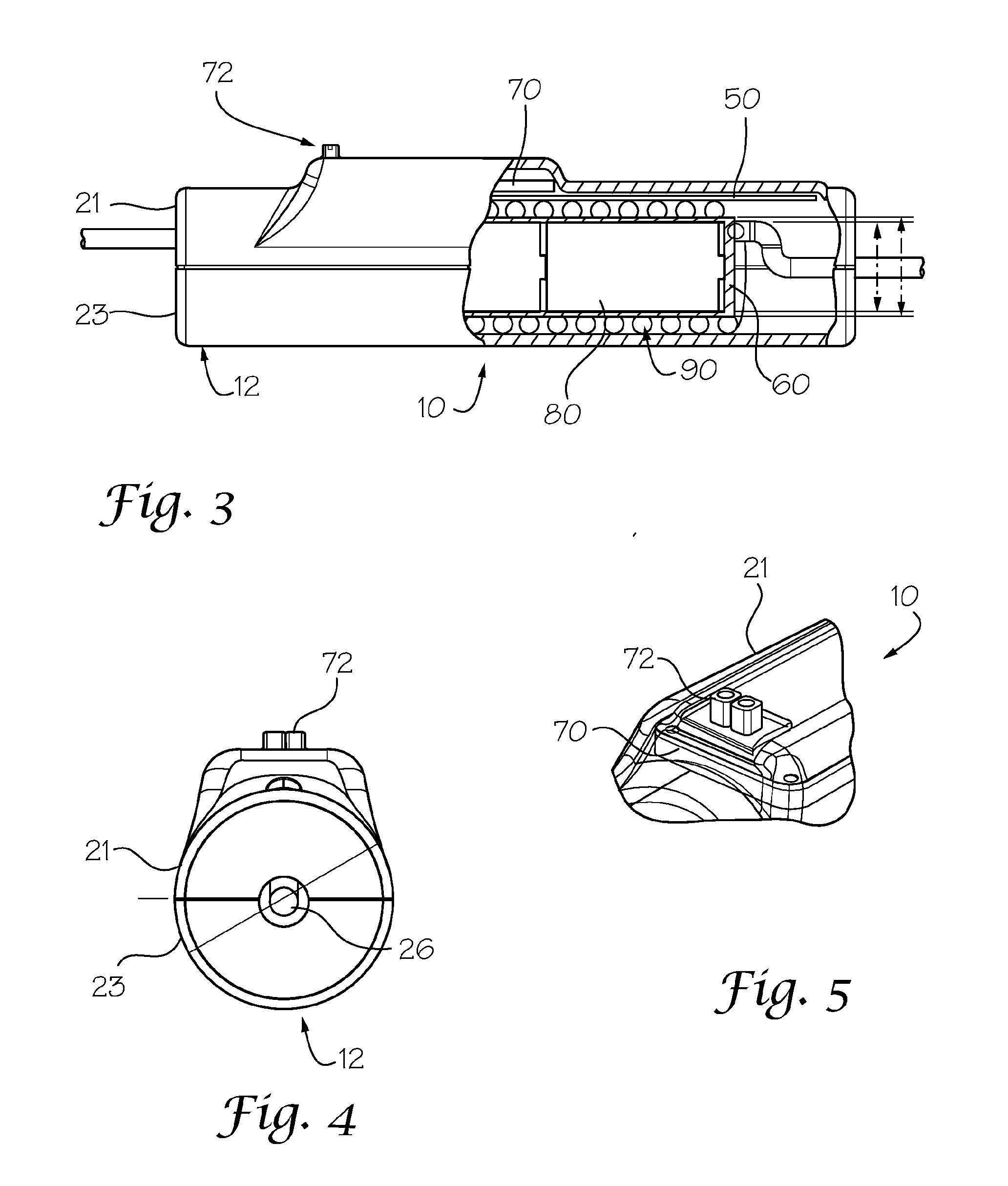
[0061]With reference to the drawings, the invention will now be described in more detail. An intravenous fluid heater device is dimensioned to be wearable on the patient such as to be located adjacent to an infusion situs (i.e., the location on the patient's body were the fluid is to be infused into the patient), and is also configured to determine automatically when, and to provide a visual warning if, the fluid flow rate in the intravenous fluid heater device falls below a desired minimum threshold therefore, and / or gas (e.g., air) is present in the fluid. The intravenous fluid heater device has particular utility for supplying an intravenous fluid to patient at flow rates of between about 50 ml / hour to about 4500 ml / hour for an intravenous fluid to be heated to an infusion temperature of between about 38 and about 42 degrees Centigrade (° C.) from an input temperature of between about 1° C. and about 42° C. It should be understood that the intravenous fluid heater device of the p...


PUM


Abstract

A compact and highly efficient intravenous fluid heater includes a heat exchanger assembly, sensors for sensing respective temperatures of entering and exiting fluids of the flow path, a controller for controlling the heat generated by the heat exchanger assembly, based upon the temperatures of the exiting fluids, heating of the fluid in the flow path by the heating element so as to cause the fluid in the flow path to be substantially uniformly heated to a desired infusion temperature prior to exiting the heater. The heat exchanger assembly uses thin film heating elements having a predetermined set temperature and that transfers heat directly to a standard intravenous tube coil wrapped around the battery housing. The intravenous fluid heater is located in a housing with the intravenous fluid lines extending there from for standard connection with an intravenous line or source of intravenous fluid.

Description

CROSS REFERENCE TO RELATED APPLICATIONS [0001]This application claims the benefit of priority from U.S. Provisional Application No. 61 / 353,469.BACKGROUND OF THE INVENTION [0002]1) Field of the Invention[0003]The present invention relates to an intravenous fluid warmer and, in particular, relates to an intravenous fluid warmer that is particularly suitable for use in warming fluids and the management of hypothermia in wilderness, combat and other extreme weather and / or remote environments and locations.[0004]2) Description of Related Art[0005]Intravenous (IV) fluid heaters or warmers have traditionally been powered by an AC power source because of the high power required to heat IV fluids. Battery powered IV fluid warmer have heretofore had poor performance because of the battery sources which have been available.[0006]One known battery-powered blood or IV fluid warmer is marketed as the Thermal Angel® and is produced by Estill Medical Technologies, Inc. having an address of 4144 N. ...

Claims


Application Information

Patent Timeline
IPC IPC(8): A61M5/44
CPCA61F2007/0078A61F7/0085
Inventor SAUNDERS, DARREL BURTONECHLIN, ROBERT CHARLES
Owner NORTH AMERICAN RESCUE PRODS
Why Eureka
Try Eureka