Shower head assembly and thin film deposition apparatus comprising same

a technology of thin film deposition and shower head, which is applied in the direction of lighting and heating apparatus, dental surgery, combustion types, etc., can solve the problems of relatively low uniformity of deposited thin film, relatively slow deposition rate, and inability of atomic layer deposition apparatus to realize chemical vapor deposition process, etc., to achieve the effect of improving economic efficiency and improving apparatus efficiency

Inactive Publication Date: 2012-09-06
WONIK IPS CO LTD
View PDF37 Cites 108 Cited by
  • Summary
  • Abstract
  • Description
  • Claims
  • Application Information

AI Technical Summary

Benefits of technology

[0011]In accordance with the exemplary embodiments, the atomic layer deposition process and the chemical vapor deposition process may be performed using one a...

Problems solved by technology

However, a rate of deposition is relatively slow.
However, uniformity of the deposited thin film is relatively low.
However, since the atomic layer deposition apparatus (revolver type) according to the related art includes a plurality of single showerheads, the atomic layer deposition apparatus does not r...

Method used


Image

  • Shower head assembly and thin film deposition apparatus comprising same
  • Shower head assembly and thin film deposition apparatus comprising same
  • Shower head assembly and thin film deposition apparatus comprising same

Examples


Embodiment Construction

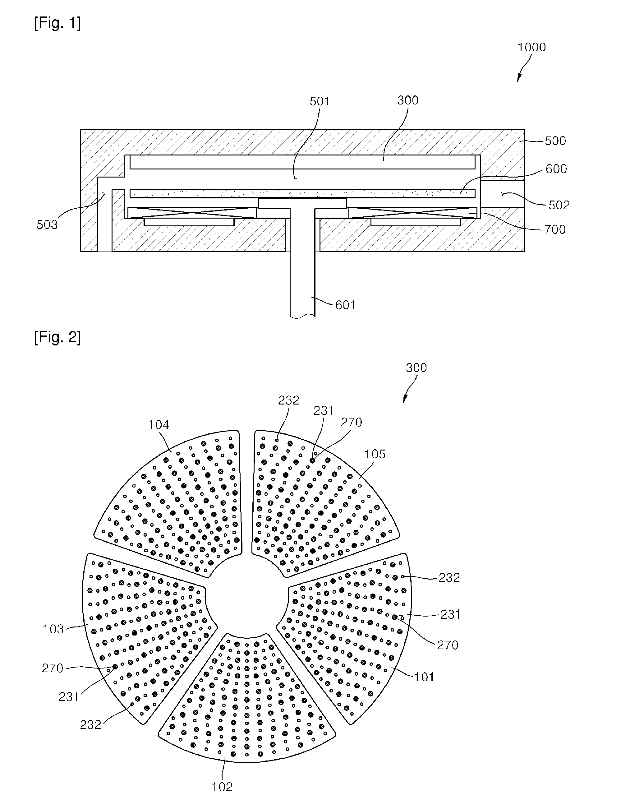
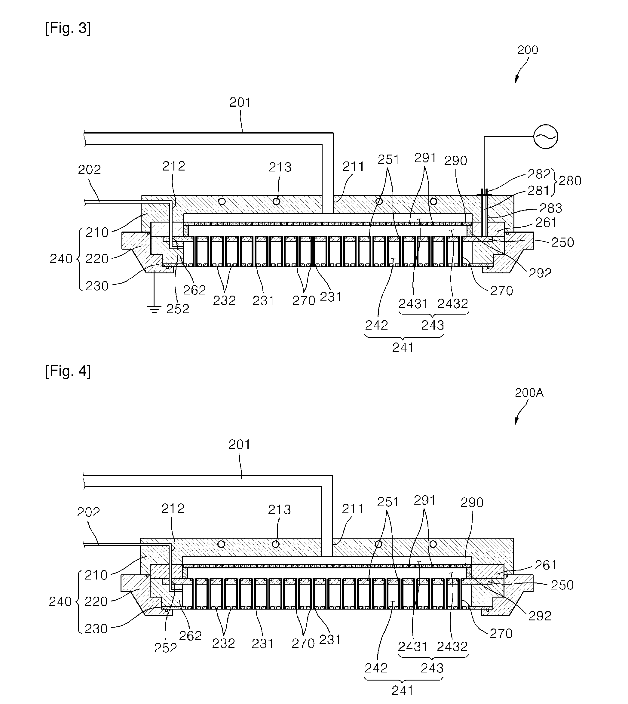
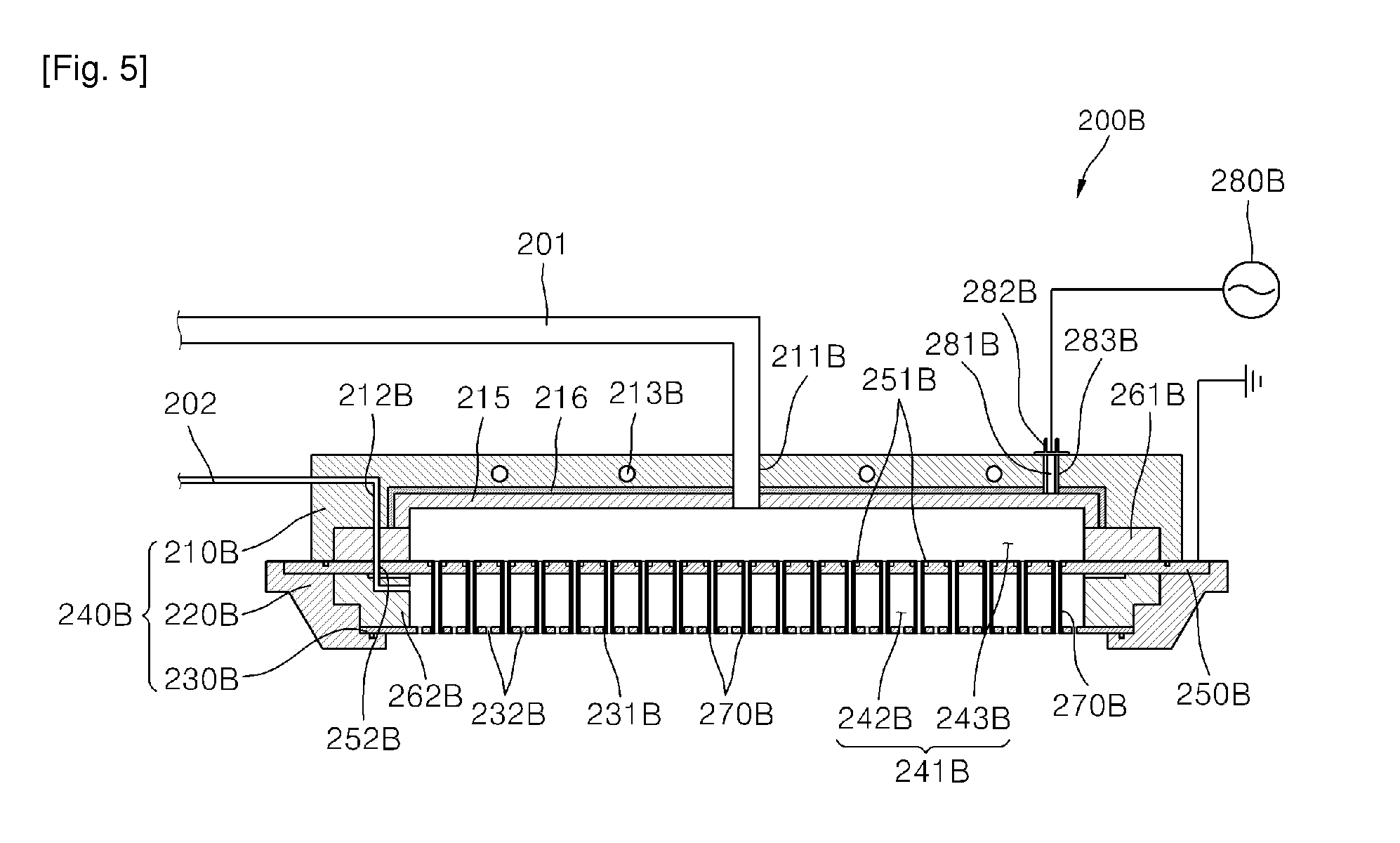
[0018]FIG. 1 is a sectional view of a thin film deposition apparatus in accordance with an exemplary embodiment. FIG. 2 is a plan view of a showerhead assembly illustrated in FIG. 1. FIG. 3 is a sectional view of a gas injection unit for generating plasma illustrated in FIG. 2.

[0019]Referring to FIGS. 1 to 3, a thin film deposition apparatus 1000 in accordance with an exemplary embodiment includes a chamber 500, a susceptor 600, a heater part 700, and a showerhead assembly 300.

[0020]A space part 501 in which a deposition process is performed on a substrate is defined in the chamber 500. Also, the chamber 500 has a gate through which the substrate enters or exits to load / unload the substrate and an exhaust passage 503 for discharging gases within the chamber 500.

[0021]The susceptor 600 has a flat plate shape, and the substrate is seated on the susceptor 600. The susceptor 600 is coupled to a driving shaft 601 and disposed in the space part 501 so that the susceptor 600 is elevated an...


PUM

PropertyMeasurementUnit
Poweraaaaaaaaaa
Shapeaaaaaaaaaa

Abstract

Provided are a showerhead assembly for depositing a thin film on a substrate and a thin film deposition apparatus having the same. The showerhead assembly includes a plurality of gas injection units radially disposed above a substrate, each of the plurality of gas injection units comprising a receiving part configured to receive a gas supplied from the outside and a plurality of injection holes configured to inject the gas within the receiving part. Here, at least one gas injection unit includes the receiving part defined therein, a showerhead body comprising a first inlet configured to supply a first gas into the receiving part and a second inlet configured to supply a second gas into the receiving part, the showerhead body comprising a plurality of first injection holes and a plurality of second injection holes in a bottom part thereof, wherein the first and second injection holes pass through the bottom part, a partition plate having a flat plate shape and comprising a plurality of insertion holes passing therethrough, the partition plate being disposed facing the bottom plate of the showerhead body in the receiving part of the showerhead body to divide the receiving part into a first buffer part communicating with the first inlet and a second buffer part communicating with the second inlet, a plurality of injection pins, each having a hollow shape, each of the plurality of injection pines comprising one end connected to the insertion hole and the other end connected to the first injection hole, and a power source configured to apply a power to generate plasma within the receiving part of the showerhead body.

Description

TECHNICAL FIELD[0001]The present disclosure relates to a showerhead assembly for depositing a thin film on a substrate and a thin film deposition apparatus having the same, and more particularly, to a showerhead assembly for depositing a thin film using a reaction gas and a source gas and a thin film deposition apparatus having the same.BACKGROUND ART[0002]A semiconductor manufacturing process includes a deposition process for depositing a thin film on a wafer or substrate. An atomic layer deposition apparatus and a chemical vapor deposition apparatus may be used as an apparatus for performing the deposition process.[0003]The atomic layer deposition apparatus is an apparatus in which a source gas, a purge gas, a reaction gas, and a purge gas are successively injected onto a substrate (wafer) to deposit a thin film. The atomic layer deposition apparatus may have an advantage that the thin film can be uniformly deposited on the substrate. However, a rate of deposition is relatively sl...

Claims


Application Information

Patent Timeline
IPC IPC(8): C23C16/50B05B1/14
CPCC23C16/4401C23C16/45536C23C16/509C23C16/45574C23C16/45565H01L21/205
Inventor HAN, CHANG-HEERYU, DONG-HOLEE, KI-HOON
Owner WONIK IPS CO LTD
Why Eureka
Try Eureka