Aircraft seating arrangement

a seating arrangement and aircraft technology, applied in the direction of seating arrangements, aircraft crew accommodation, movable seats, etc., can solve the problems of large quantity, general undesirable configuration, and difficulty in large quantity, so as to save space, efficiently provide seating throughout the aircraft fuselage, and save space in the linear direction

Active Publication Date: 2012-09-06
BE AEROSPACE INCORPORATED
View PDF4 Cites 99 Cited by
  • Summary
  • Abstract
  • Description
  • Claims
  • Application Information

AI Technical Summary

Benefits of technology

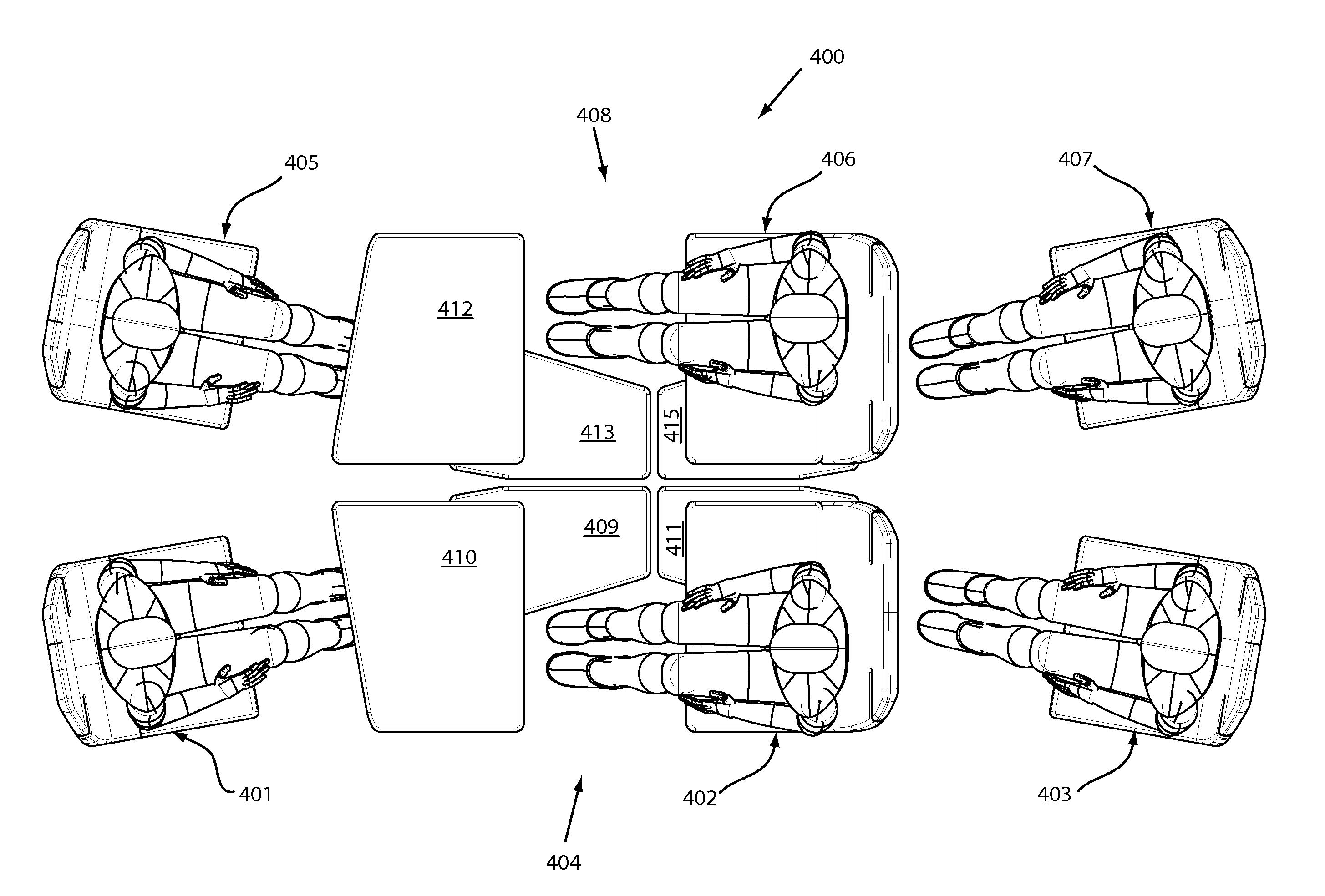
[0016]In an example embodiment, two three-seat groupings can be combined to form a six-seat module that allows unobstructed access to all seating assemblies, conserves space and efficiently provides seating throughout an aircraft fuselage. Each three-seat grouping can be arranged so that one or both lower seat assemblies are disposed in parallel with, or alternatively, at an angle with respect to the upper seat assembly. When combined to form a six-seat grouping, the upper seats may be facing the same direction (aft or forward) or may face opposite directions. In an example embodiment, a six-seat grouping having aligned seats is configured to angle a lower passenger across a lie-flat seat thereby conserving space in the linear direction.
[0017]An example embodiment can include a six-seat module comprising two upper seats, two lower seats that face the same direction as the upper seats, and two lower seats that oppose the upper seats. While all lower seating can be aligned with the upper seating, disposition of footwells for lower opposing passengers, due to a sharing of footspace with upper passengers, can angle occupants in a lie-flat position; while disposition of footwells for lower non-opposing passengers can allow a passenger to lie straight.
[0018]An example vehicle seating assembly can include a support assembly structure, and a seat movably attached to the support assembly structure, the seat including a seatback and a seat base for supporting a passenger. An exemplary seating assembly can include a vertical member configured to extend between the support assembly structure and a vehicle ceiling structure to provide stability to said seating assembly. In an exemplary embodiment, the vertical member is in the form of a generally vertical support configured for attachment to the seat shell and a vehicle ceiling structure. In an example embodiment the vertical member is adapted to attach to a ceiling beam of an aircraft fuselage. The vertical member reduces the load on the vehicle floor when a force is applied the seating assembly. The vertical member is particularly advantageous when used with a seating assembly that provides an elevated seat.
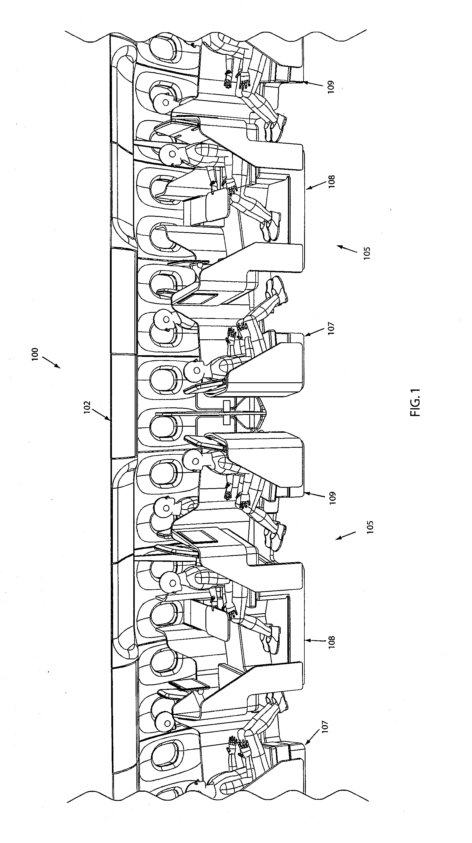
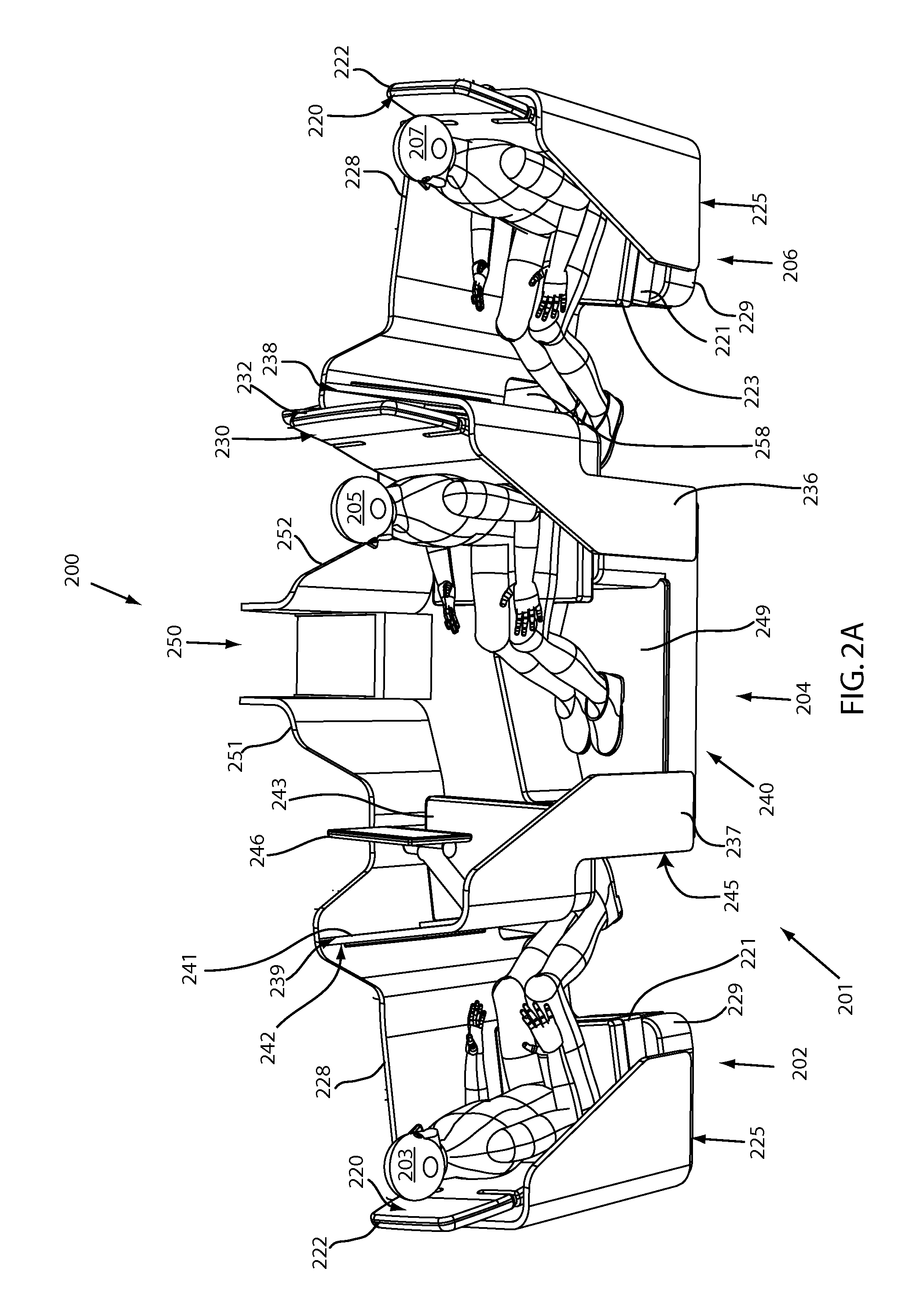
[0019]In an example embodiment, a seating arrangement includes a three-seat grouping having a vertical member. The three-seat grouping can include a fore-facing lower seating assembly providing a seat convertible between a sitting position and a lie flat position in a lower horizontal plane, an aft-facing lower seating assembly providing a seat convertible between a sitting position and a lie flat sleeping position in the lower horizontal plane, an upper seating assembly positioned between the fore-facing and aft-facing lower seating assemblies providing a seat convertible between a sitting position and a lie flat position in an upper horizontal plane, and a vertical member configured to attach to said upper seat assembly and an aircraft ceiling structure to provide stability to said upper seating assembly. The two lower seating assemblies and the single upper seating assembly can form a three-seat grouping in which fore- and aft-facing lower seats underlap an upper center seat when extended in a lie flat position. The vertical member can strengthen and stabilize the upper seat assembly, reducing its structural load and improving the ability of the seating structure and the floor beneath it to withstand applied forces. The lower seating assemblies can be aligned with, or angled with respect to the upper seating assembly.
[0020]In an example embodiment, an aircraft fuselage is configured to accommodate one or more seating assemblies comprising a vertical member. By way of example, but not limitation, storage compartments associated with the seating assemblies can be disposed at the ground or seating level, eliminating the need for overhead storage. Seating level storage offers several advantages, including but not limited to, increased passenger headroom above the seats, improved storage compartment accessibility by passengers and crew, and improved safety as the potential hazard of falling items from overhead bins is eliminated. In addition, the absence of overhead storage compartments facilitates vertical member mounting and allows the use of raised seating near the side of the fuselage which is typically restricted by the curvature of the fuselage. In an exemplary embodiment a seating arrangement includes a storage compartment associated with each seat. The storage compartment can be sized and configured to accommodate carry-on items. A storage compartment for a first passenger can be integrated with a seating assembly of a second passenger to reduce the amount of space required to provide sufficient storage for each passenger.

Problems solved by technology

While such lie-flat seating provides additional comforts to passengers, and allows airlines to charge higher fares, lie-flat seating requires additional space, making it difficult to provide in large quantity.
While fit for their intended purposes, the prior art arrangements are plagued by several drawbacks and disadvantages.
For example, in some prior art seating arrangements, the seat of a first passenger covers the head of a second passenger, a generally undesirable configuration.
Other prior art arrangements fail to efficiently utilize horizontal and / or vertical space, decreasing the cost effectiveness of the arrangement.
Arrangements designed to conserve space can require one passenger to crawl over another passenger to enter or exit a seat, a process that can be uncomfortable for both the moving and seated passengers.
Not only is this inconvenient for both passengers but it may also lead to difficulties during an emergency.
Raised seating arrangements also generally cause greater loads to be applied to the floor, and thus require heavier, and more substantial and expensive support structures to satisfy airline safety requirements.

Method used


Image

  • Aircraft seating arrangement
  • Aircraft seating arrangement
  • Aircraft seating arrangement

Examples


Embodiment Construction

[0070]As required, exemplary embodiments of the present invention are disclosed herein. These embodiments are meant to be examples of various ways of implementing the invention and it will be understood that the invention may be embodied in alternative forms. The figures may not be to scale and some features may be exaggerated or minimized to show details of particular elements, while related elements may have been eliminated to prevent obscuring novel aspects. Therefore, specific structural and functional details disclosed herein are not to be interpreted as limiting, but merely as a basis for the claims and as a representative basis for teaching one skilled in the art to variously employ the present invention. The terms “fore” and “aft” are used merely for orientational purposes in reference to the particular exemplary embodiments shown in the drawings. Furthermore, the term lie-flat may mean substantially flat which could be angled and not necessarily horizontal.

[0071]For purpose...


PUM


Abstract

A vehicle seating arrangement can comprise a fore-facing lower seating assembly, an aft-facing lower assembly, and an upper seating assembly positioned between the fore-facing and aft-facing lower assemblies. The lower and upper assemblies can be configured to form a 3-seat unit in which a portion of a seat of said fore-facing and aft-facing lower seat assemblies underlaps a portion of an upper seating assembly. At least one of the fore-facing and aft-facing lower assemblies can be angled with respect to the upper seating assembly to shorten the overall linear dimension of the 3-seat unit and provide egress areas for lower passengers to aisle access. A vertical member can be configured to attach to the upper seating assembly and to a ceiling structure to reduce the load on the floor.

Description

CROSS REFERENCE TO RELATED APPLICATIONS[0001]This application claims the benefit of U.S. Provisional Application No. 61 / 382,477 entitled “Aircraft Seating Arrangement” filed Sep. 13, 2010, by Henshaw, and U.S. Provisional Application No. 61 / 449,026, entitled “Aircraft Seating Arrangement”, filed Mar. 3, 2011 by Henshaw, both of which are incorporated herein in their entirety by reference.FIELD OF INVENTION[0002]The present invention relates to seating and seating arrangements for passenger vehicles, and more particularly, to aircraft seating arrangements in which seats can be converted between an upright position and a lie-flat sleeping position.BACKGROUND OF INVENTION[0003]Optimizing an aircraft seating arrangement includes maximizing seating capacity while attending to passenger comfort. Generally, the more spacious and comfortable a seat, the more an airline can charge for the seat, but the fewer the number of seats that can be provided.[0004]A traditional aircraft seat includes ...

Claims


Application Information

Patent Timeline
Patent Type & Authority Applications(United States)
IPC IPC(8): B64D11/06B60N2/02B60N2/34B60N2/01
CPCB64D11/06B64D11/064B64D11/0641B64D11/0606B64D11/0601B64D11/0604B64D2011/0069B64D11/00153B60N2/01B64D11/00151
Inventor HENSHAW, ROBERT J.
Owner BE AEROSPACE INCORPORATED
Why Eureka
Try Eureka