Sterilization system with ultraviolet emitter for eradicating biological contaminants

Active Publication Date: 2012-09-06
FLAHERTY KAREN
View PDF14 Cites 108 Cited by
  • Summary
  • Abstract
  • Description
  • Claims
  • Application Information

AI Technical Summary

Benefits of technology

[0019]In another exemplary version, the sterilization system uses UV-C light as a target designator of biological contaminants via the use of low power UV-C light “headlights” or “taillights” in conjunction with on-board optical sensors to detect levels of illumination around the sterilization system, and which can be used to both target the location of the biological contaminants and estimate the strength of the biological contaminants based upon their illumination, so that a proper combination of on-board eradication methodologies can be used to effectively sterilize and destroy the surface biological contaminants in the shortest timeframe and using the optimal energy resources within the invention.
[0020]Exemplary sterilization systems include self-contained robotic devices for the eradication of biological contaminants found on floor surfaces which use UV light emission technology in multiple distinct protoc

Problems solved by technology

In the role of target designator for the sterilization system, these lower powered UV headlights can cause biological contaminants on surfaces around the ster

Method used


Image

  • Sterilization system with ultraviolet emitter for eradicating biological contaminants
  • Sterilization system with ultraviolet emitter for eradicating biological contaminants
  • Sterilization system with ultraviolet emitter for eradicating biological contaminants

Examples


Embodiment Construction

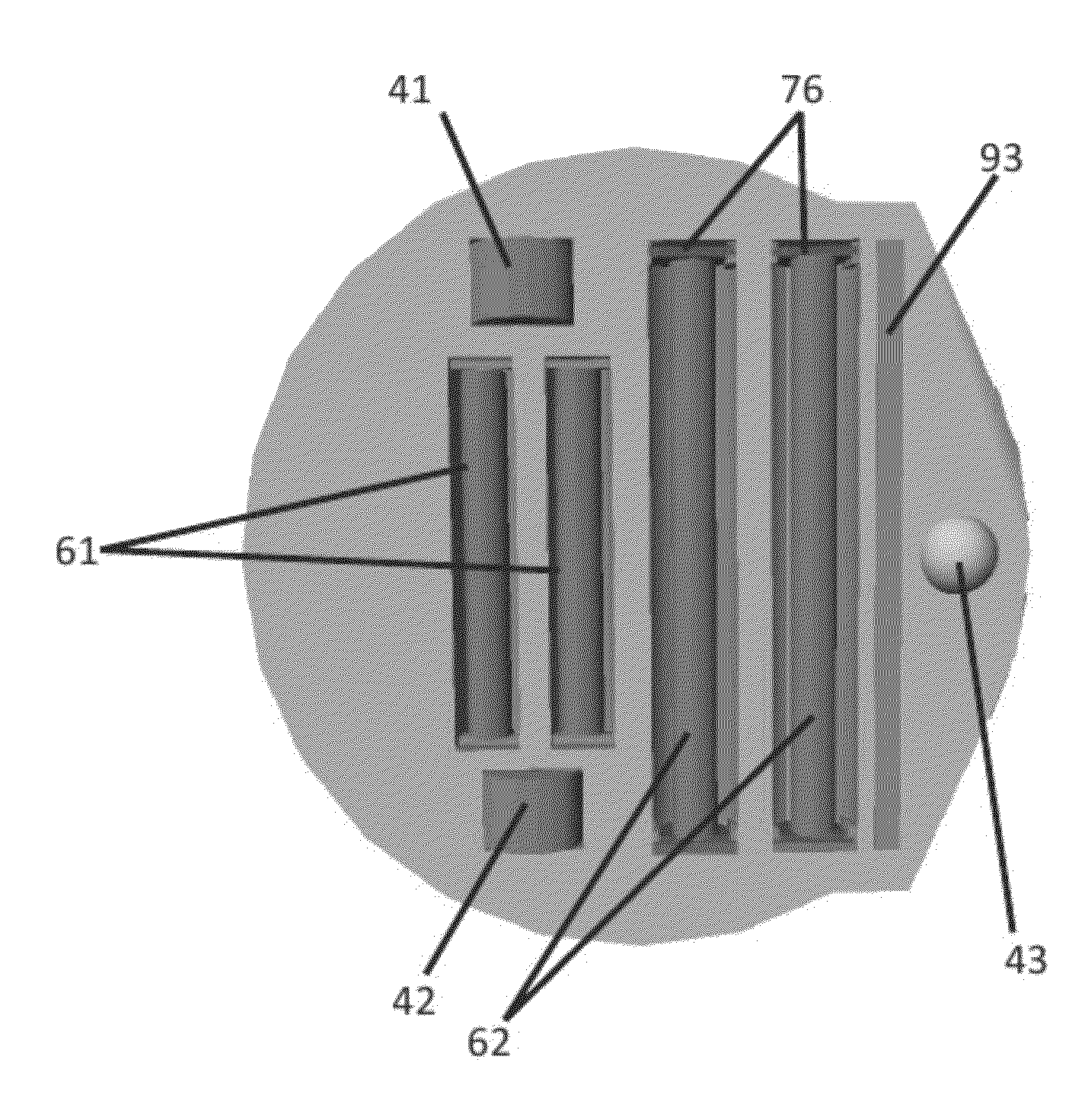
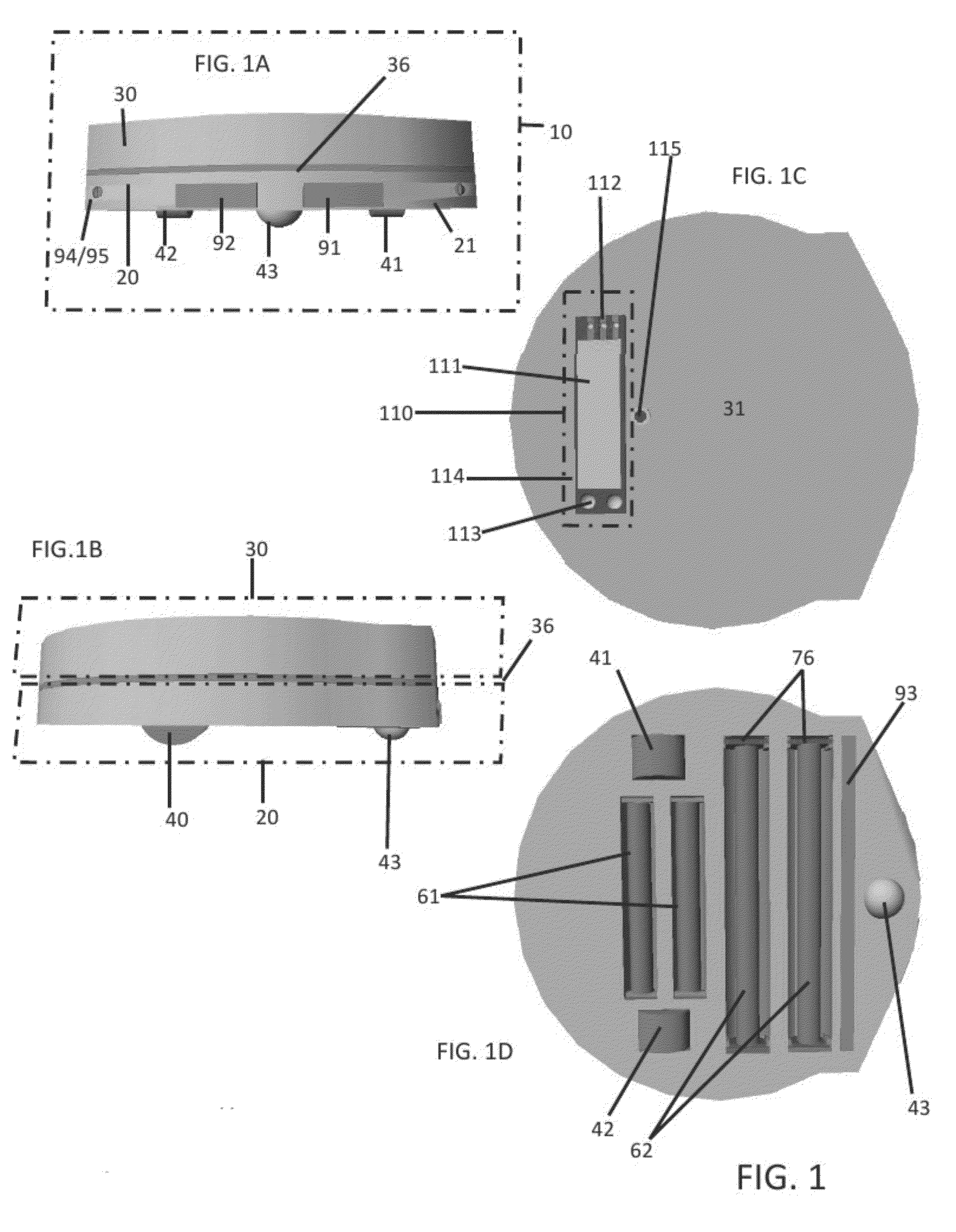
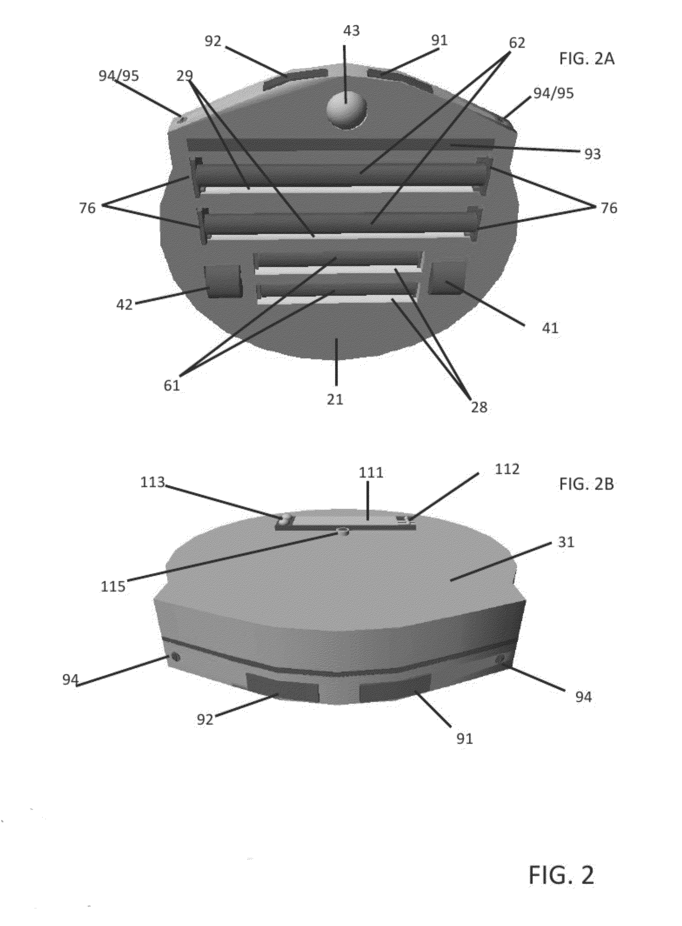
[0128]As seen in FIGS. 1A through 1D, an exemplary Sterilization system 10 has a lower half which is the Main Body 20 and an upper half which is the Top Cover 30. The two halves join at a center line 36 which allows the Top Cover 30 to hide and protect the interior components which reside in the Main Body 20 of the Sterilization system 10. On the top surface of the Top Cover 30 is the Control Panel 110. The Control Panel 110 is the main “command and control unit” of the Sterilization system 10 and is used to issue commands for the control of the basic functions of the Sterilization system 10.

[0129]The Control Panel 110 is connected to the Computer Core 58 of the Motion Management System 50 via a detachable electrical USB Connector 33. USB Connector 33, as shown in FIG. 5A, extends from the bottom 116 of the Control Panel 110 so that it inserts into the USB Connector 64 on the Motion Management System 50 component. The connection between the control Panel 110 and the Computer Core 58...


PUM


Abstract

An exemplary sterilization system includes a self-propelled robotic mobile platform for locating and eradicating infectious bacterial and virus strains on floors (and objects thereon), walls, cabinets, angled structures, etc., using one or more ultraviolet light sources. A controller allows the system to adjust the quantity of ultraviolet light received by a surface by, for example, changing the intensity of energy input to a ultraviolet light source, changing a distance between a ultraviolet light source and a surface being irradiated, changing the speed/movement of the mobile platform to affect time of exposure, and/or by returning to contaminated areas for additional passes. The mobile platform may include a sensor capable of detecting fluorescence of biological contaminants irradiated with ultraviolet light to locate contaminated areas. The system is thus capable of “seek and destroy” functionality by navigating towards contaminated areas and irradiating those areas with ultraviolet light accordingly.

Description

CROSS-REFERENCE TO RELATED APPLICATIONS[0001]This application claims priority under 35 USC §119(e) to U.S. Provisional Patent Application 61 / 464,362 filed Feb. 24, 2011, the entirety of which is incorporated by reference herein.FIELD OF THE INVENTION[0002]Exemplary versions of the invention relate generally to self-contained devices created for the eradication of biological microorganisms and contaminants found on surfaces in public and private places, such as, for example, gymnasiums (such as gym floors and athletic floor mats), schools, daycares, hospitals, government buildings, homes, etc. Additionally, versions of the invention relate to a self-propelled, autonomous, robotic system which utilizes ultraviolet (UV) light as its eradication technology for the sterilization of infectious bacterial and virus strains on surfaces. Moreover, versions of the invention relate to a robotic device which utilizes sensors in conjunction with an internal computer logic system to both navigate ...

Claims


Application Information

Patent Timeline
IPC IPC(8): A61L2/10
CPCA47L2201/04A47L2201/06A61L2/10A61L2/24G05D2201/0203A61L2202/16A61L2202/25G05D1/0242A61L2202/14
Inventor FLAHERTY, PATRICKWINKLER, BRUCE L.GOLD, ROBERT J.
Owner FLAHERTY KAREN
Why Eureka
Try Eureka