Check patentability & draft patents in minutes with Patsnap Eureka AI!

Method and apparatus for minimizing overlay errors in lithography

a technology of overlay errors and lithography, applied in special data processing applications, optics, instruments, etc., can solve problems such as overall error correction effort, and achieve the effects of reducing the overlay minimizing the pattern placement error of each mask, and reducing the error of the mask s

Active Publication Date: 2012-09-06
CARL ZEISS SMS GMBH
View PDF5 Cites 41 Cited by
  • Summary
  • Abstract
  • Description
  • Claims
  • Application Information

AI Technical Summary

Benefits of technology

[0014]According to a first aspect of the invention, a method for minimizing errors of a plurality of photolithographic masks, wherein the plurality of photolithographic masks serving for successively processing a substrate, comprises determining a reference displacement vector field, the reference displacement vector field correlates displacement vectors of the errors of the plurality of photolithographic masks, determining for each of the photolithographic mask a difference displacement vector field as a difference between the reference displacement vector field and the displacement vectors of the errors of the respective photolithographic mask, and correcting the errors for each of the photolithographic masks using the respective difference displacement vector field or the reference displacement vector field.

Problems solved by technology

In order to reduce the overall error correction effort, the defined method does not correct the pattern placement errors of each mask separately and independently from the other masks of the mask set, but takes the pattern placement errors of the other masks of the mask set into account.

Method used


Image

  • Method and apparatus for minimizing overlay errors in lithography
  • Method and apparatus for minimizing overlay errors in lithography
  • Method and apparatus for minimizing overlay errors in lithography

Examples


first embodiment

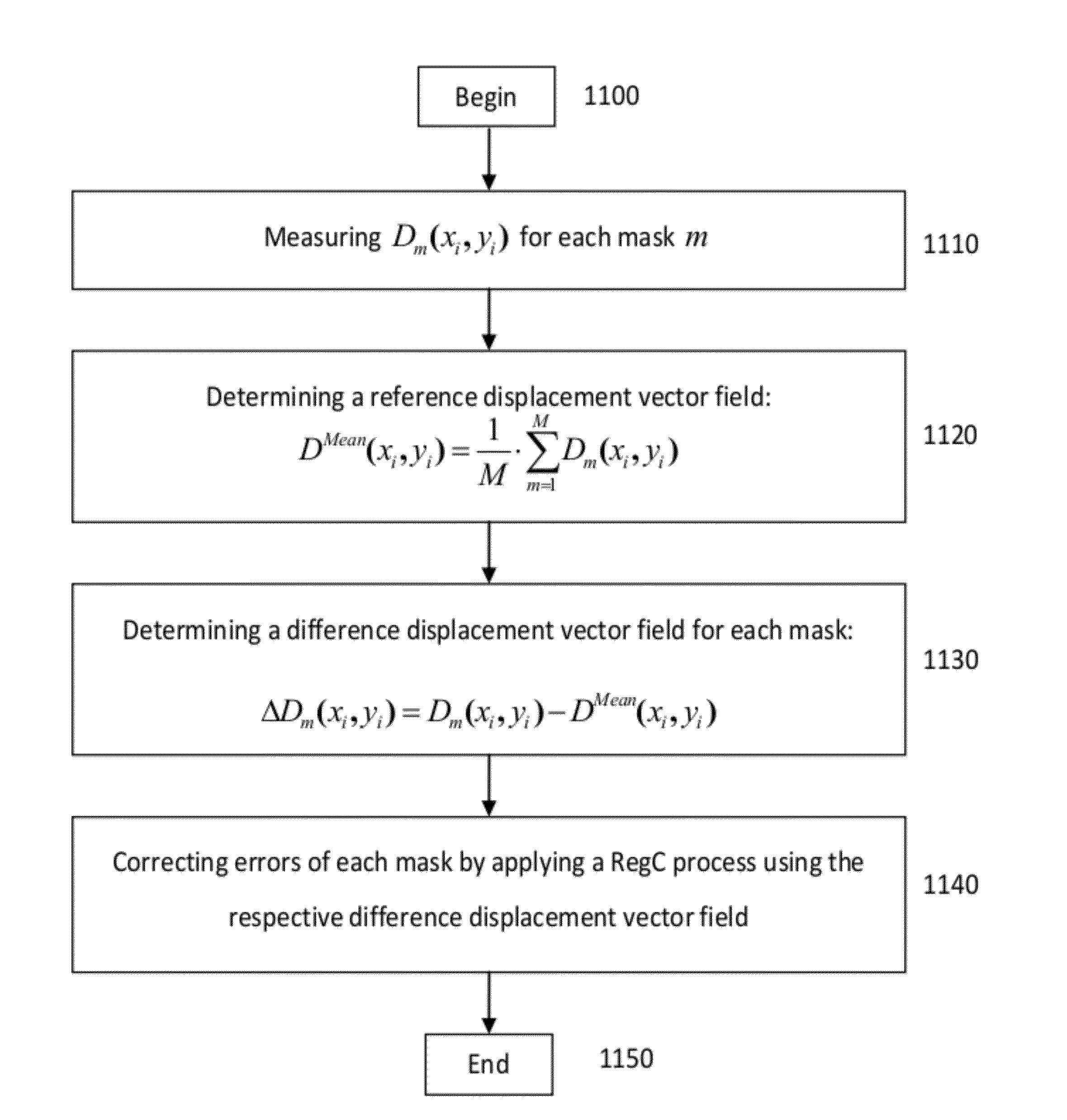
[0107]FIG. 11 shows a flow diagram summarizing the above discussed embodiment of the inventive method. The flow starts at box 1100. First step 1110 is measuring of the registration. In a second step 1120, a reference displacement vector field is calculated according to a generalized version of equation 3. In the subsequent step 1130 a difference displacement vector field is calculated for each mask of the mask set according to equation 4. Finally, in step 1140, the difference displacement vector fields are used in a RegC process to correct placement errors of each mask of the mask set. The flow of the first embodiment ends at step 1150.

[0108]The second exemplary embodiment, discussed in the following, differs from the first example discussed above in to that the reference displacement vector field is determined in a different manner. In the second example, one mask of the mask set is used as a reference and the other ones are corrected so that they show the same pattern placement er...

second embodiment

[0109]FIGS. 12a and 12b represent a flow diagram of the The flow begins at 1200, and as a first step 1205 the placement errors are measured for each mask. In a second step 1210, the difference displacement vectors for the mask combination m and n are defined at the position i by the equation:

ΔDmn(xi,yi)=Dmn(xi,yi)−Dn(xi,yi)  (5)

where Dm(xi,yi) is defined in equation 2. Then, at step 1215, an average displacement value ΔDmnAvr of the absolute values of the difference displacement vectors ΔDmn(xi,yi) for the mask combination m and n is determined by averaging ΔDmn(xi,yi) across the number of grid nodes i according to the equation:

ΔDmnAvr=1Q·∑i=1QΔDmn(xi,yi)(6)

[0110]In step 1220, parallel to the calculation of the average displacement value ΔDmnAvr according to equation 6, the maximum displacement value ΔDmnMax of the absolute values of the difference displacement vectors of the mask combination m and n is calculated according to the relation:

ΔDmnMax=Max1≤i≤Q(ΔDmn(xi,yi))(7)

which desc...

third embodiment

[0118]FIGS. 13a and 13b illustrate the flow diagram of the After begin at 1300, placement vectors Dm(xi,yi) of registration errors of each mask m of a set are measured at step 1305. At step 1310, a RegC correction process is simulated for the placement errors Dm(xi,yi). The displacement errors remaining after performing the simulation of the RegC correction process are referred to as the corrected displacement vector field DmCorr(xi,yi). At step 1320, an iteration index k is set to its initial value (k=1).

[0119]In step 1325, a difference correction displacement vector field ΔDmCorr(xi,yi) is determined for the combination of the masks m and n defined by:

ΔDmnCorr(xi,yi)=DmCorr(xi,yi)−DnCorr(xi,yi)  (13)

[0120]At step 1335, for each mask m average difference correction displacement vectors are determined by averaging the norms of the difference correction displacement vector ΔDmnCorr(xi,yi) at the position i with all masks n of the mask set according to:

ΔDmCorr,Avr(xi,yi)=1(M-1)·∑n=1,...


PUM


Abstract

The invention relates to a method for minimizing errors of a plurality of photolithographic masks, the plurality of photolithographic masks serving for successively processing a substrate, the method comprises determining a reference displacement vector field, the reference displacement vector field correlates displacement vectors of the errors of the plurality of photolithographic masks, determining for each of the photolithographic mask a difference displacement vector field as a difference between the reference displacement vector field and the displacement vectors of the errors of the respective photolithographic mask, and correcting the errors for each of the photolithographic masks using the respective difference displacement vector field.

Description

CROSS-REFERENCE TO RELATED APPLICATION[0001]Pursuant to 35 U.S.C. §120, this application claims priority to U.S. provisional application 61 / 448,253, filed on Mar. 2, 2011. The content of the above application is incorporated by reference in its entirety.FIELD OF THE INVENTION[0002]The present invention relates to the field of minimizing overlay errors in lithography.BACKGROUND OF THE INVENTION[0003]As a result of the steadily increasing integration density of semiconductor devices, photolithographic masks or templates for nanoimprint lithography have to transfer smaller and smaller features. To meet this demand, the actinic wavelength of the imaging tool has been reduced in steps of 436 nm and 365 nm to 193 nm. Furthermore, immersion lithography has been introduced to enlarge the numerical aperture of the projection systems. As a consequence, the mask manufacturing process has reached a very high degree of complexity accompanied with strongly enlarged costs. In the near future, refl...

Claims


Application Information

Patent Timeline
IPC IPC(8): G06F17/50
CPCG03F1/70G03F7/70633
Inventor PFORR, RAINER
Owner CARL ZEISS SMS GMBH
Features
  • R&D
  • Intellectual Property
  • Life Sciences
  • Materials
  • Tech Scout
  • Unparalleled Data Quality
  • Higher Quality Content
  • 60% Fewer Hallucinations
Learn More