Heat pump system for vehicle

Active Publication Date: 2012-09-13
HANON SYST
View PDF6 Cites 52 Cited by
  • Summary
  • Abstract
  • Description
  • Claims
  • Application Information

AI Technical Summary

Benefits of technology

[0024]Furthermore, the heat pump system further includes: a branch line for connecting a refrigerant circulation line of the second indoor heat exchanger and the first bypass line with each other; a second bypass line, which bypasses an outdoor heat exchanger; and a control part that controls a flow of the indoor air to be introduced into an air-conditioning case, so that the heat pump system can minimize influences of the outdoor air of low temperature even when the outdoor temperature is below zero, enhance the operation and the heating performance of the heat pump system by collecting waste heat of the vehicle electric devices and heat sources of the indoor air, and increase the mileage of the vehicle by minimizing operation of an electric heater.
[0025]Moreover, the heat pump system collects the waste heat of the vehicle electric devices and heat sources of the outdoor air when the outdoor temperature is above zero and collects the waste heat of the vehicle electric devices and heat sources of the indoor air when the outdoor temperature is below zero, and provides various modes, such as the maximum heating mode, the heating mode, the dehumidification mode and the defrost mode during operation in the heat pump mode according to thermal loads and purposes, so that the heat pump system can enhance and keep its efficiency and heating performance and minimize operation of the electric heater to thereby increase the mileage of the vehicle.
[0026]Additionally, in the dehumidification

Problems solved by technology

Furthermore, in order to solve the problem of degradation of performance in the condition that the outdoor temperature is low, there is an attempt to install an electric heater (not shown) inside the air-conditioning case 10 as a main heating device or an auxiliary heating device, but in the case that the electric heater is used

Method used


Image

  • Heat pump system for vehicle
  • Heat pump system for vehicle
  • Heat pump system for vehicle

Examples


Embodiment Construction

[0039]Reference will be now made in detail to the preferred embodiment of the present invention with reference to the attached drawings.

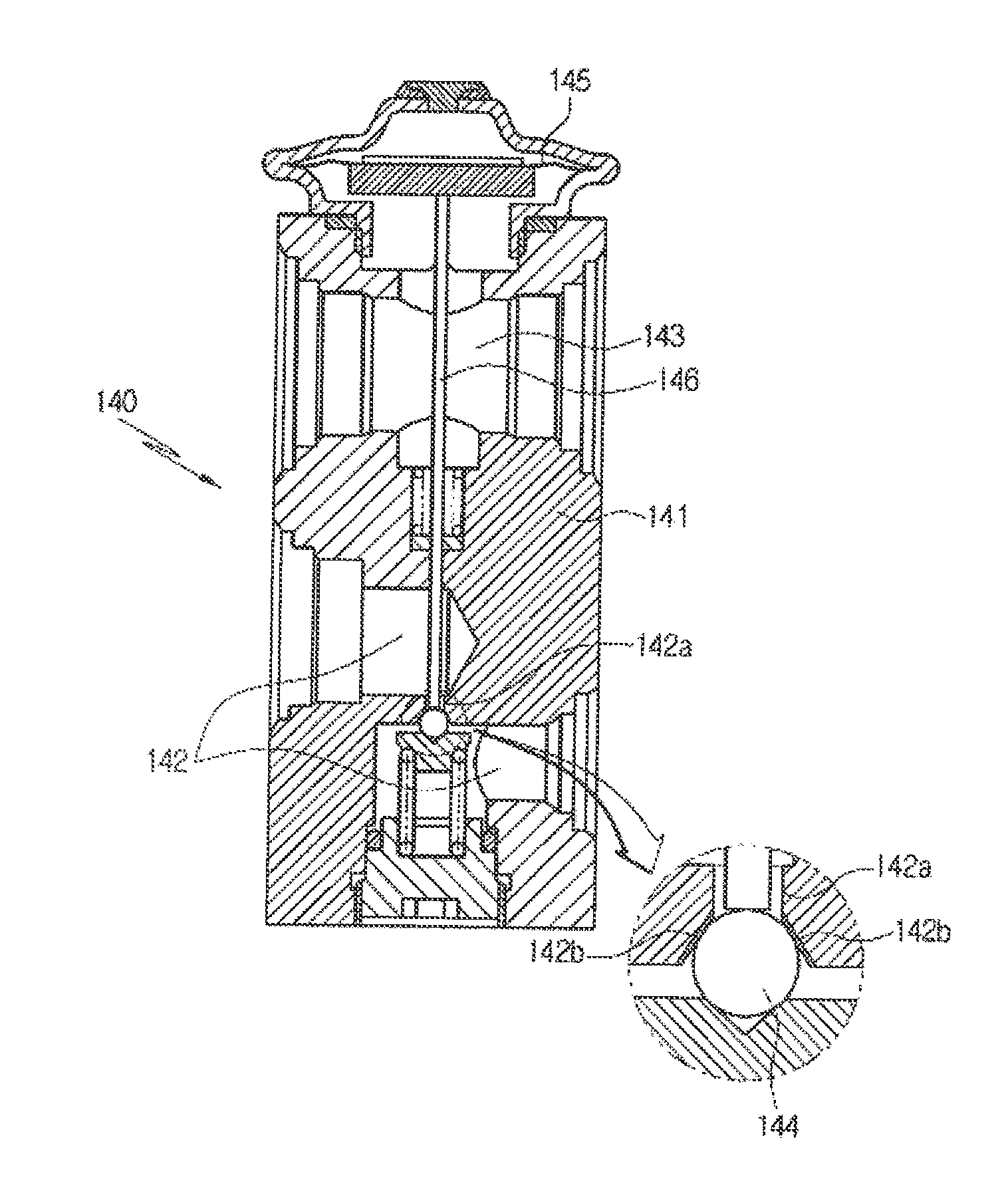
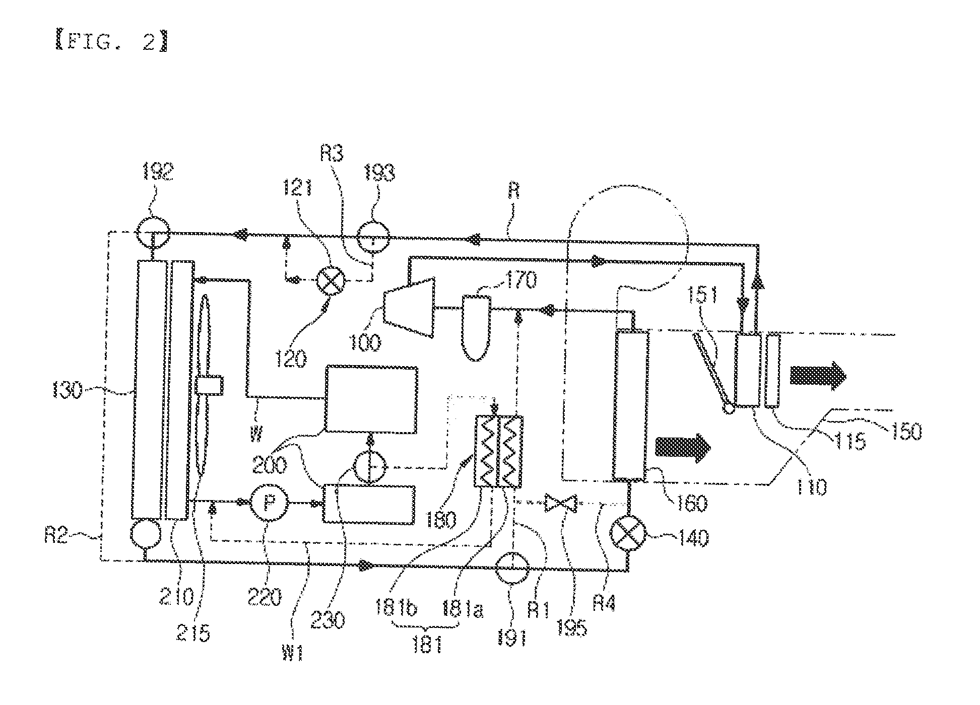
[0040]First, a heat pump system for a vehicle according to the present invention includes a compressor 100 mounted on a refrigerant circulation line R of an air-conditioning system, first indoor heat exchanger 110, a second expansion means 120, an outdoor heat exchanger 130, a first expansion means 140, and a second indoor heat exchanger 160 connected with one another in order. The heat pump system for the vehicle according to the present invention is preferably applied to electric vehicles or hybrid vehicles,

[0041]Moreover, on the refrigerant circulation line R, a first bypass line R1 which bypasses the second indoor heat exchanger 160, a second bypass line R2 which bypasses the outdoor heat exchanger 130, and an expansion line R3 constituting the second expansion means 120 are mounted in parallel. In addition, a first direction-switching valve 191...


PUM


Abstract

A heat pump system including a water-cooled type heat exchanger, which is a heat supply means, mounted on a first bypass line bypassing a second indoor heat exchanger to collect waste heat of vehicle electric devices to thereby enhance a heating efficiency of the heat pump system. The heat pump system for a vehicle includes: a branch line for connecting a refrigerant circulation line of the second indoor heat exchanger and the first bypass line with each other; a second bypass line, which bypasses an outdoor heat exchanger; and a control part that controls a flow of the indoor air to be introduced into an air-conditioning case, whereby the heat pump system can minimize influences of the outdoor air of low temperature even when the outdoor temperature is below zero, enhance the operation and the heating performance of the heat pump system by collecting waste heat of the vehicle electric devices and heat sources of the indoor air, and increase the mileage of the vehicle by minimizing operation of an electric heater.

Description

BACKGROUND OF THE INVENTION[0001]1. Field of the Invention[0002]The present invention relates to a heat pump system for a vehicle, and more particularly, to a heat pump system for a vehicle that includes: a water-cooled type heat exchanger, which is a heat supply means, mounted on a first bypass line, which bypasses a second indoor heat exchanger (evaporator), for collecting waste heat of vehicle electric devices; a branch line for connecting a refrigerant circulation line of the second indoor heat exchanger and the first bypass line with each other; and a second bypass line, which bypasses an outdoor heat exchanger.[0003]2. Background Art[0004]An air conditioner for a vehicle generally includes a cooling system for cooling the inside of the vehicle and a heating system for heating the inside of the vehicle. The cooling system exchanges heat between air, which passes through the outside of an evaporator near the evaporator of a refrigerant cycle, and refrigerant, which flows inside ...

Claims


Application Information

Patent Timeline
IPC IPC(8): F25B13/00F25B27/02
CPCB60H1/00921B60H2001/00949B60H2001/00307B60H1/143B60H1/22B60H1/32F25B30/02F25B47/02
Inventor WANG, YOONHOKANG, SUNGHOSEO, JEONGHUNLIM, YOUNWOOKIM, HAKKYU
Owner HANON SYST
Why Eureka
Try Eureka