

antenna
a small antenna and antenna technology, applied in the field of small antennas, can solve the problems of insufficient radiation electrode length, insufficient antenna characteristics, and large batteries in wireless apparatuses, and achieve the effect of good antenna characteristics and high gain
- Summary
- Abstract
- Description
- Claims
- Application Information
AI Technical Summary
Benefits of technology
Problems solved by technology
Method used
Image

Examples
example 1
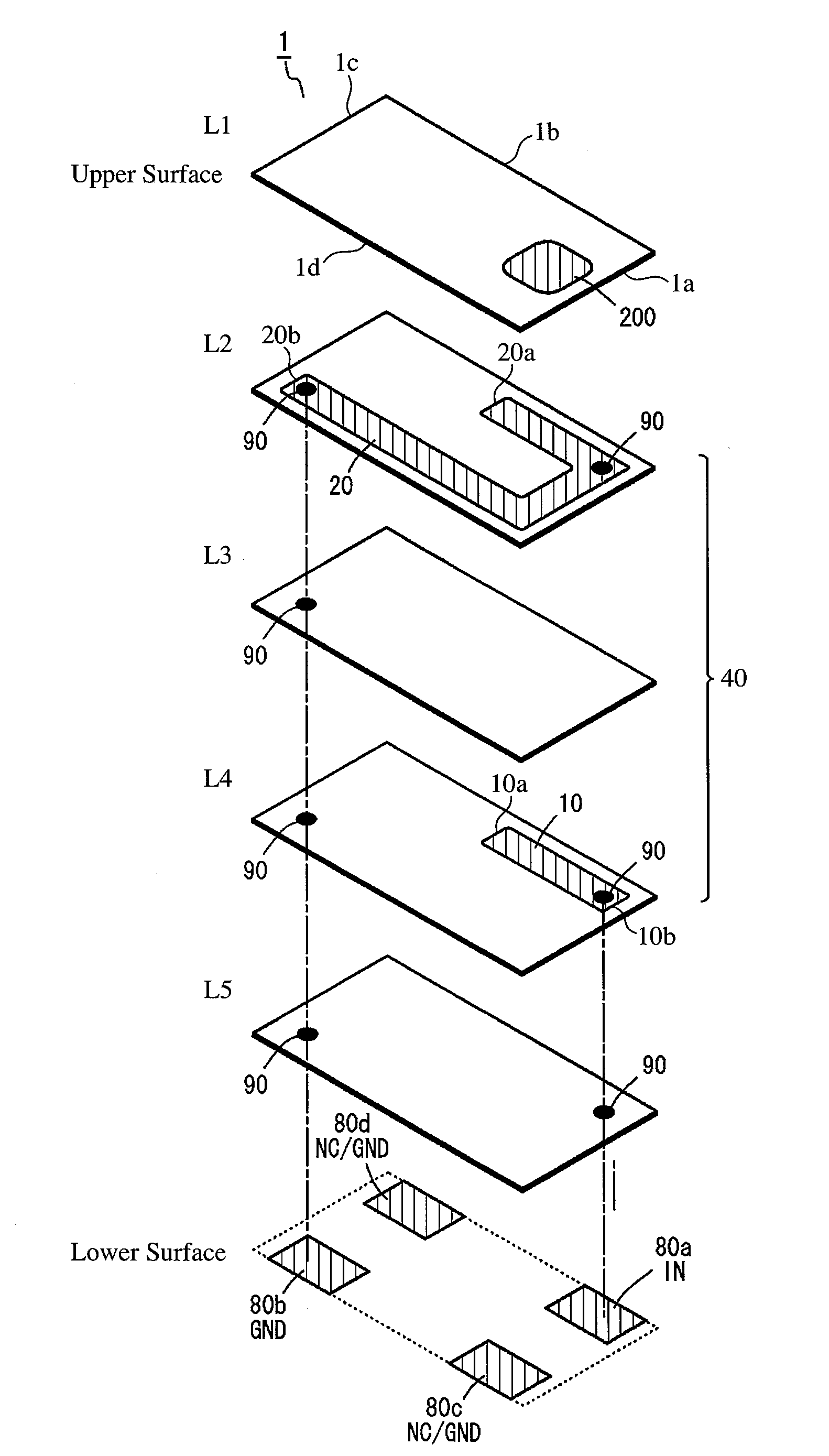
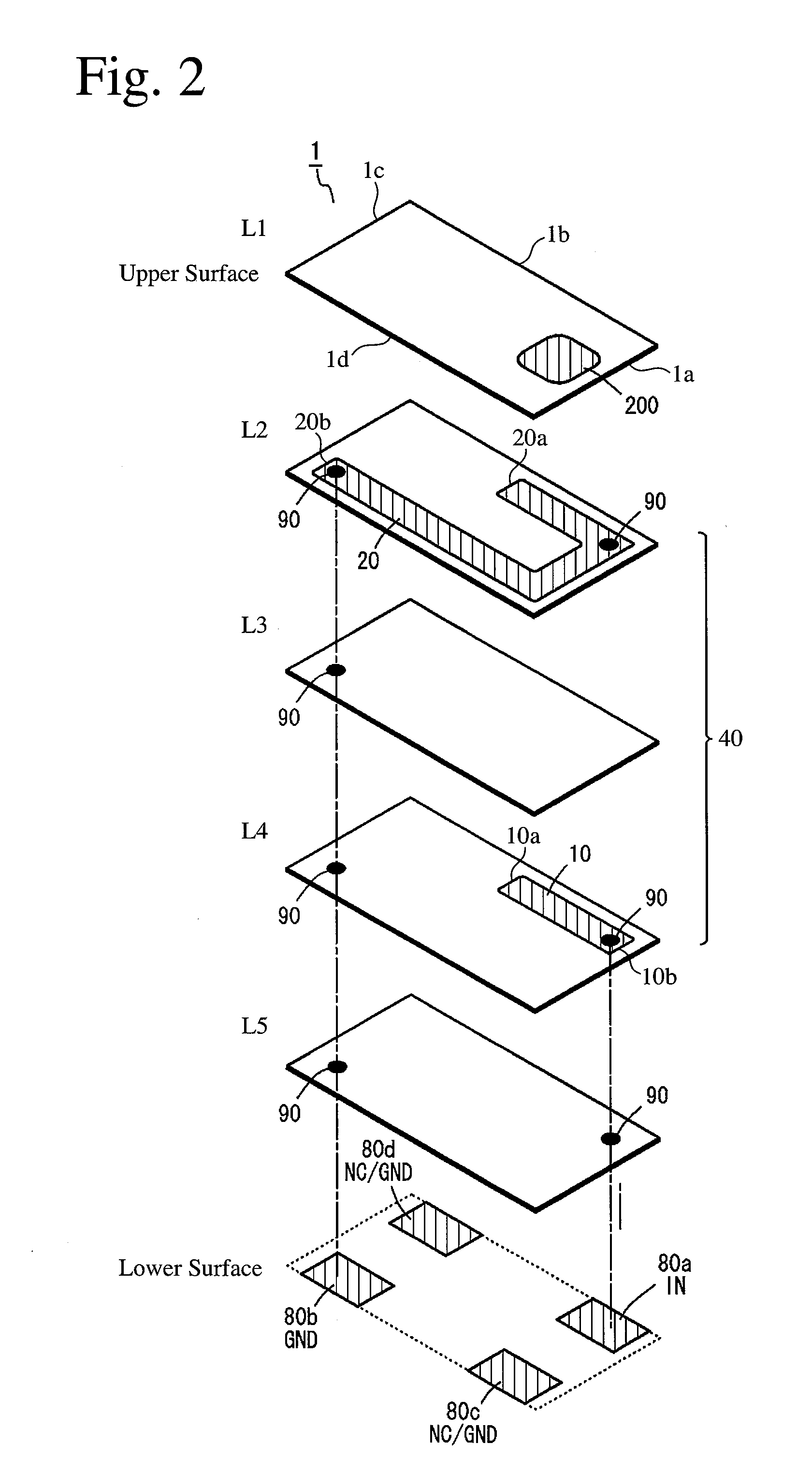
[0072]Using a dielectric Al—Si—Sr ceramic having a dielectric constant ∈r of 8, a laminate for a Bluetooth / WLAN antenna used in a frequency band of 2.4-2.5 GHz, which had the basic structure shown in FIG. 9, was produced by the following method. First, Al2O3 powder, SiO2 powder, SrCO3 powder, TiO2 powder, Bi2O3 powder, Na2CO3 powder and K2CO3 powder were uniformly wet-mixed by a ball mill, to have a post-sintering composition comprising 100% by mass of main components comprising 50% by mass of Al2O3, 36% by mass of SiO2, 10% by mass of SrO, and sub-components comprising 4% by mass of TiO2 2.5% by mass of Bi2O3, 2% by mass of Na2O and 0.5% by mass of K2O. The resultant mixture was calcined, pulverized, granulated, and then molded to ceramic green sheets having various thicknesses by a doctor blade method.
[0073]Each ceramic green sheet was screen-printed with a silver paste in an electrode pattern, laminated to have the structure shown in FIG. 9, and sintered at 820° C. to produce a m...
example 2
WLAN Antenna for 2.4-GHz Band and 5-GHz Band
[0076]A laminate 1 having the same basic structure as in Example 1 was mounted by soldering on the board 90 (L=90 mm, W=45 mm, La=38.5 mm, Lb=38.5 mm, L1=13 mm, and L2=6 mm) shown in FIG. 26. Formed on the board 90 were a 6-mm-long first line electrode 30a connected to the second terminal electrode 80b of the laminate 1, and a 4-mm-long second line electrode 30b connected to the third terminal electrode 80c of the laminate 1. The first line electrode 30a was provided with a chip capacitor C1 (1.0 pF) as a reactance element 50. Thus, the first line electrode 30a constituted an additional radiation electrode, making the antenna usable in a 2.4-GHz band.
[0077]The second line electrode 30b soldered to a third terminal electrode 80c not connected to the radiation electrode 20 of the laminate 1 was connected to a feed line via capacitance between the first terminal electrode 80a and the third terminal electrode 80c and capacitance between the ra...
example 3
GPS / WLAN Antenna for 1.5-GHz Band and 2.4-GHz Band
[0079]A laminate 1 having the same basic structure as in Example 1, in which a sub-radiation electrode portion 22 was as long as 2.5 mm, a coupling electrode 10 was as long as 2.5 mm, and gap between the sub-radiation electrode portion 22b and the coupling electrode 10 was 100 μm, was mounted on the board 90 shown in FIG. 28 by soldering. Formed on the board 90 were a first line electrode 30a connected to the second terminal electrode 80b of the laminate 1 and a second line electrode 30b connected to the third terminal electrode 80c of the laminate 1. The board 90 had the same L, W, La, Lb, L1, L2, and lengths of the line electrode 30 and the second line electrode 30b as in Example 2.
[0080]The first line electrode 30a soldered to the second terminal electrode 80b connected to the radiation electrode 20 of the laminate 1 was provided with a chip capacitor C1 (10 pF) as a reactance element 50. Thus, the first line electrode 30a constit...
PUM
 Abstract
Description
Claims
Application Information