Method and device for encoding image data, and method and device for decoding image data

a technology of image data and encoding method, applied in signal generators with optical-mechanical scanning, color television with bandwidth reduction, etc., can solve the problems of increasing the pressure on the distribution network, and increasing the data rate, so as to reduce the risk of errors.

Active Publication Date: 2012-09-13
CANON KK
View PDF6 Cites 70 Cited by
  • Summary
  • Abstract
  • Description
  • Claims
  • Application Information

AI Technical Summary

Benefits of technology

[0016]In a particular embodiment the coding dependency comprises coding dependency between coding units and the slice boundaries are defined according to the coding dependency of a coding unit on its neighbouring coding units in the image. Thus, for example a slice boundary may be introduced between coding units which have a low co-dependency, and decoding will be less prone to errors.
[0018]In an embodiment at least one of the characteristics of the network is the maximum transport unit size of the network via which the encoded image is to be transmitted. This helps to increase the probability that the received packet will be decodable.
[0054]According to yet another aspect of the invention, there is provided an encoding method in which slices of an image are defined for respective decoding processes wherein a single reconstruction slice is used for each of the regions of an image with low frequencies coding blocks and regions with high frequencies coding blocks are subdivided into several reconstruction slices in order to limit the error propagation within such areas.

Problems solved by technology

This evolution in technology puts increased pressure on distribution networks that already face difficulties in providing HDTV resolution and data rates economically to the end user.
Consequently, further increases in data rate will put additional pressure on such distribution networks.
However, current HEVC techniques do not provide a solution that is flexible enough to respond to requirements of all of these applications efficiently.

Method used


Image

  • Method and device for encoding image data, and method and device for decoding image data
  • Method and device for encoding image data, and method and device for decoding image data
  • Method and device for encoding image data, and method and device for decoding image data

Examples


first embodiment

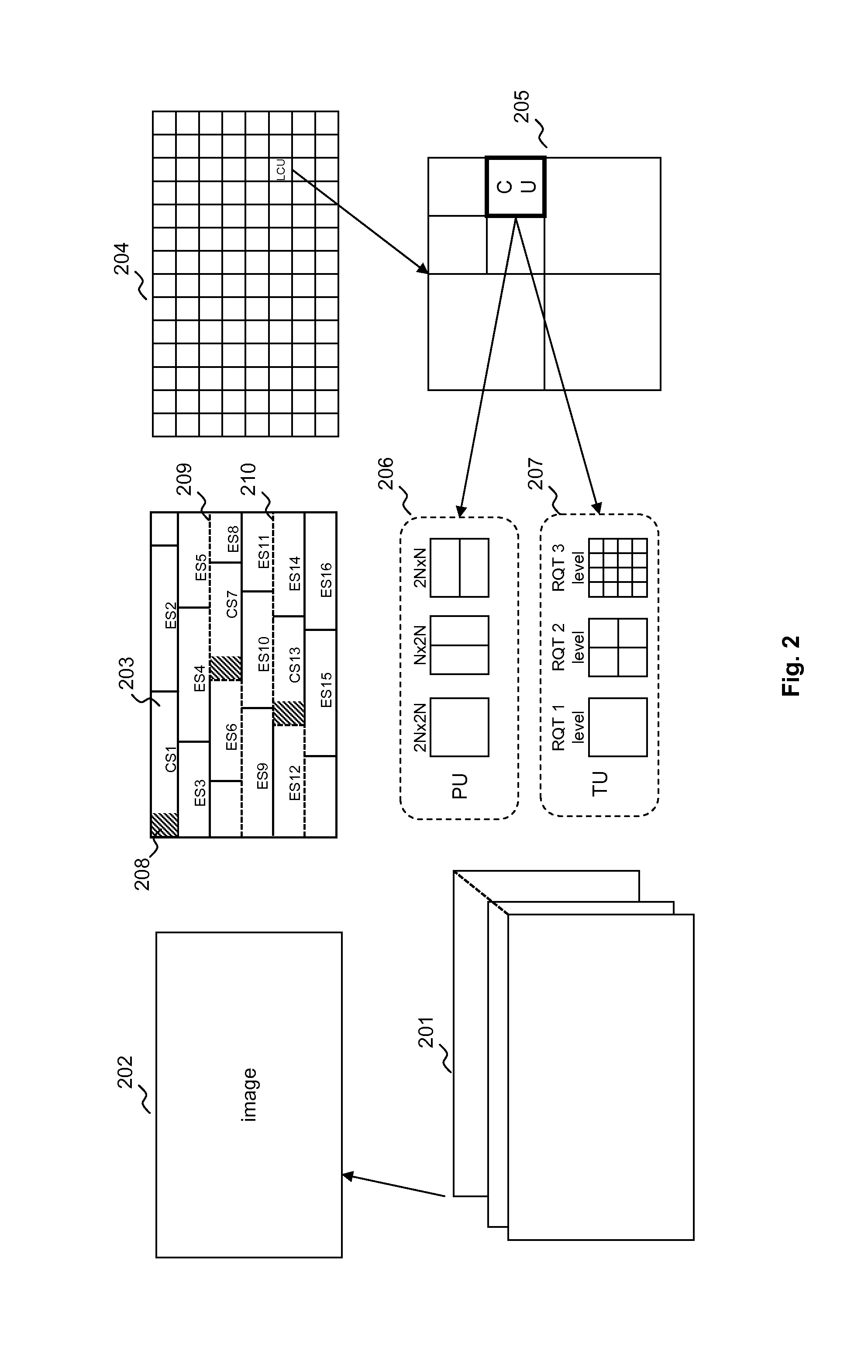
[0121]In the first embodiment, three types of coding dependency boundaries corresponding to three different types of encoding processes are considered:[0122]1. The syntax coding boundaries (503) that enable the coding dependencies for entropy coding (309) and prediction mode coding (303 and 306) sub processes to be limited. CUs that are separated with such a boundary cannot use their neighbor's CU information to code the syntax values of current CU. The set of CUs that are bounded by two syntax coding boundaries are now referred as syntax slice.[0123]2. Pixel samples reconstruction boundaries (502) that delimit spatially the dependencies with neighbor CUs for coding of pixels data (302; 304; 305; 307; 308). The encoding process of stage 302, 304 and 305 cannot use pixel data of a neighbor CU when they are separated by these boundaries. The set of CUs that are bounded by two pixel sample boundaries are now referred as reconstruction slice.[0124]3. Loop filtering boundaries (501) that...

third embodiment

[0171]FIG. 7 schematically represents NAL units that constitute the encoded bitstream in accordance with the The encoded bitstream begins with Sequence Parameter Set (702) and Picture Parameter Set (703) NAL units. Then, the encoded frame 700 starts with a slice parameter information dataset SIPS NALU 704. This NAL unit is sent prior to any NAL slice units of the frame. Then a processing slice parameter set NALU dedicated to processing parameters for reconstruction slices (705) and a processing slice parameter set NALU dedicated to processing parameters for Loop filter slices 706 are transmitted. The order of these two NALUs is not imposed and the NALU for the Loop filter slice parameter set 706 may be transmitted prior to the reconstruction slice parameter set NALU 705. For image 700, slice processing parameters are the same for the entire frame. Thus no other processing slice parameter sets NAL units are transmitted.

[0172]For new frame 701, the encoder defines new SIPS 708 and sl...


PUM


Abstract

A method of encoding an image of a video sequence, the image being represented by a plurality of coding units, the encoding comprising at least two different encoding processes for encoding the image wherein each encoding process introduces coding dependencies between coding units, the method comprising: determining a set of slice boundaries for each encoding process wherein the set of slice boundaries for each encoding process partitions the image into one or more slices for the respective encoding process, the one or more slices each including a set of coding units of the image between a pair of respective slice boundaries; the coding units of one slice being encoded independently of coding units of another of the slices of the respective encoding process; wherein the slice boundaries for each encoding process are defined as a function of at least one slice boundary defining parameter.

Description

CROSS-REFERENCES TO RELATED PATENT APPLICATIONS[0001]This application claims the benefit under 35 U.S.C. §119 of the filing date of UK Patent Application No. 1104106.8, filed 10 Mar. 2011, hereby incorporated by reference in its entirety as if fully set forth herein.FIELD OF INVENTION[0002]The present invention concerns a method and a device for encoding image data. The invention further relates to a method and a device for decoding image data and a bitstream of video data.DESCRIPTION OF BACKGROUND ART[0003]Video data is typically composed of a series of still images which are shown rapidly in succession as a video sequence to give the idea of a moving image. Video applications are continuously moving towards improved image resolution (greater number of pixels per frame, higher frame rate, higher bit-depth . . . ). A large quantity of video content is distributed in digital form via broadcast channels, digital networks and packaged media, with a continuous evolution towards improved...

Claims


Application Information

Patent Timeline
Patent Type & Authority Applications(United States)
IPC IPC(8): H04N7/12
CPCH04N19/70H04N19/119H04N19/147H04N19/13H04N19/115H04N19/436H04N19/14H04N19/164H04N19/174H04N19/82H04N19/61
Inventor OUEDRAOGO, NAELLAROCHE, GUILLAUME
Owner CANON KK
Why Eureka
Try Eureka