Optical Modulator Utilizing Unary Encoding And Auxiliary Modulator Section For Load Balancing

a technology of optical modulators and load balancing, applied in optics, instruments, electrical equipment, etc., can solve the problem of not being able to use lithium niobate-based optical devices in such a situation

Active Publication Date: 2012-09-13
CISCO TECH INC
View PDF4 Cites 42 Cited by
  • Summary
  • Abstract
  • Description
  • Claims
  • Application Information

AI Technical Summary

Benefits of technology

[0014]It is an advantage of the unary encoded-based optical modulator that a simplified fabrication process can be used to form the modulator, since each modulator section is of substantially the same length and thus requires essentially the same size electrical driving circuit (as opposed to prior arrangements where “longer” modulator sections require a more powerful driving circuit in order to provide the desired free carrier movement).
[0015]It has been discovered that when driving only an odd number of modulator sections, a current imbalance will result that creates a voltage perturbation (noise) along the modulator signal path. Thus, in accordance with an aspect of the present invention, an auxiliary modulating section is disposed adjacent to the modulator and energized in each instance that only an “odd” number of sections are being driving. The auxiliary section is isolated from the optical signal path so as to not affect the data signal being transmitted.

Problems solved by technology

Clearly, the use of lithium niobate-based optical devices in such a situation is not an option.

Method used


Image

  • Optical Modulator Utilizing Unary Encoding And Auxiliary Modulator Section For Load Balancing
  • Optical Modulator Utilizing Unary Encoding And Auxiliary Modulator Section For Load Balancing
  • Optical Modulator Utilizing Unary Encoding And Auxiliary Modulator Section For Load Balancing

Examples


Embodiment Construction

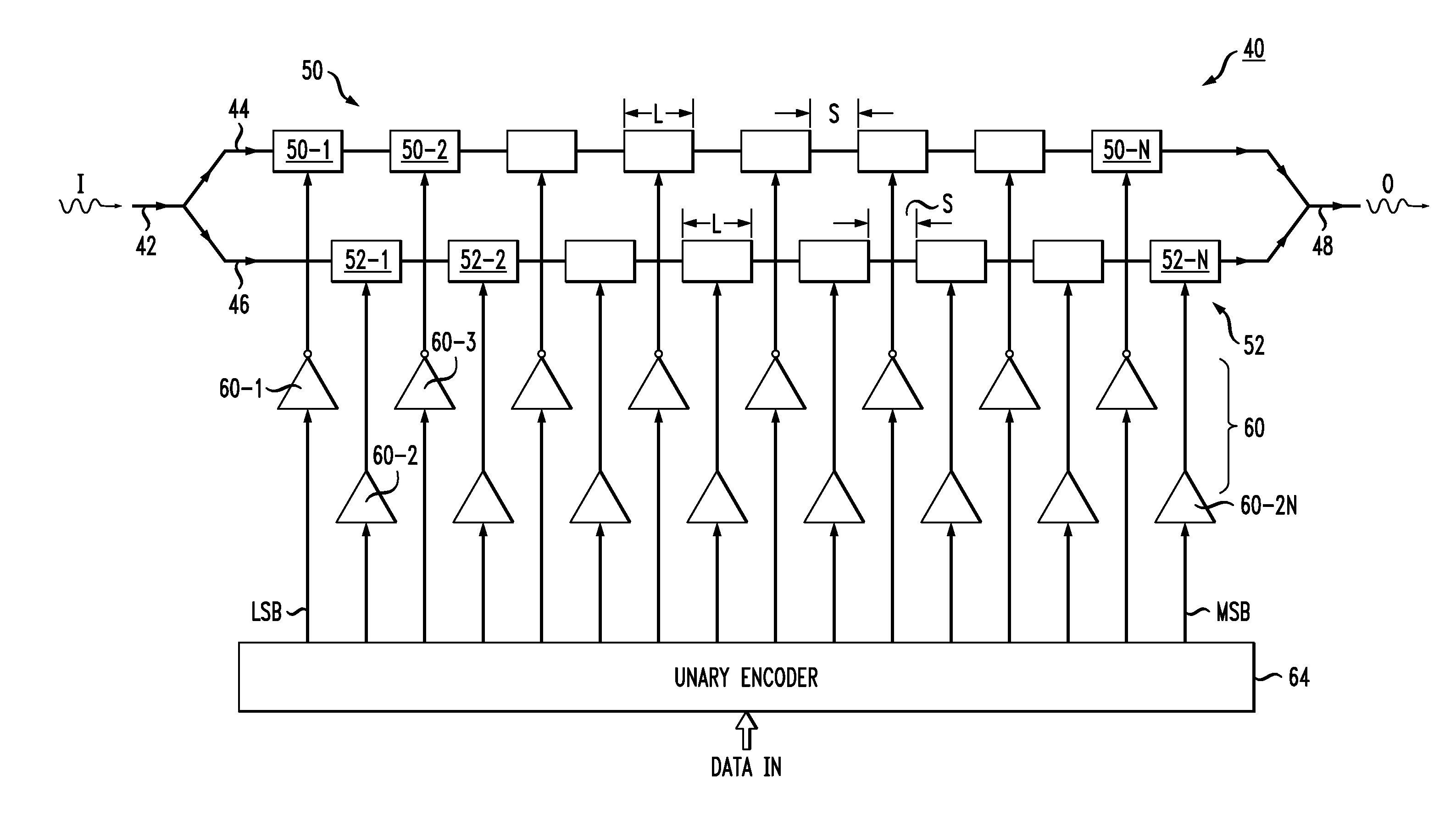
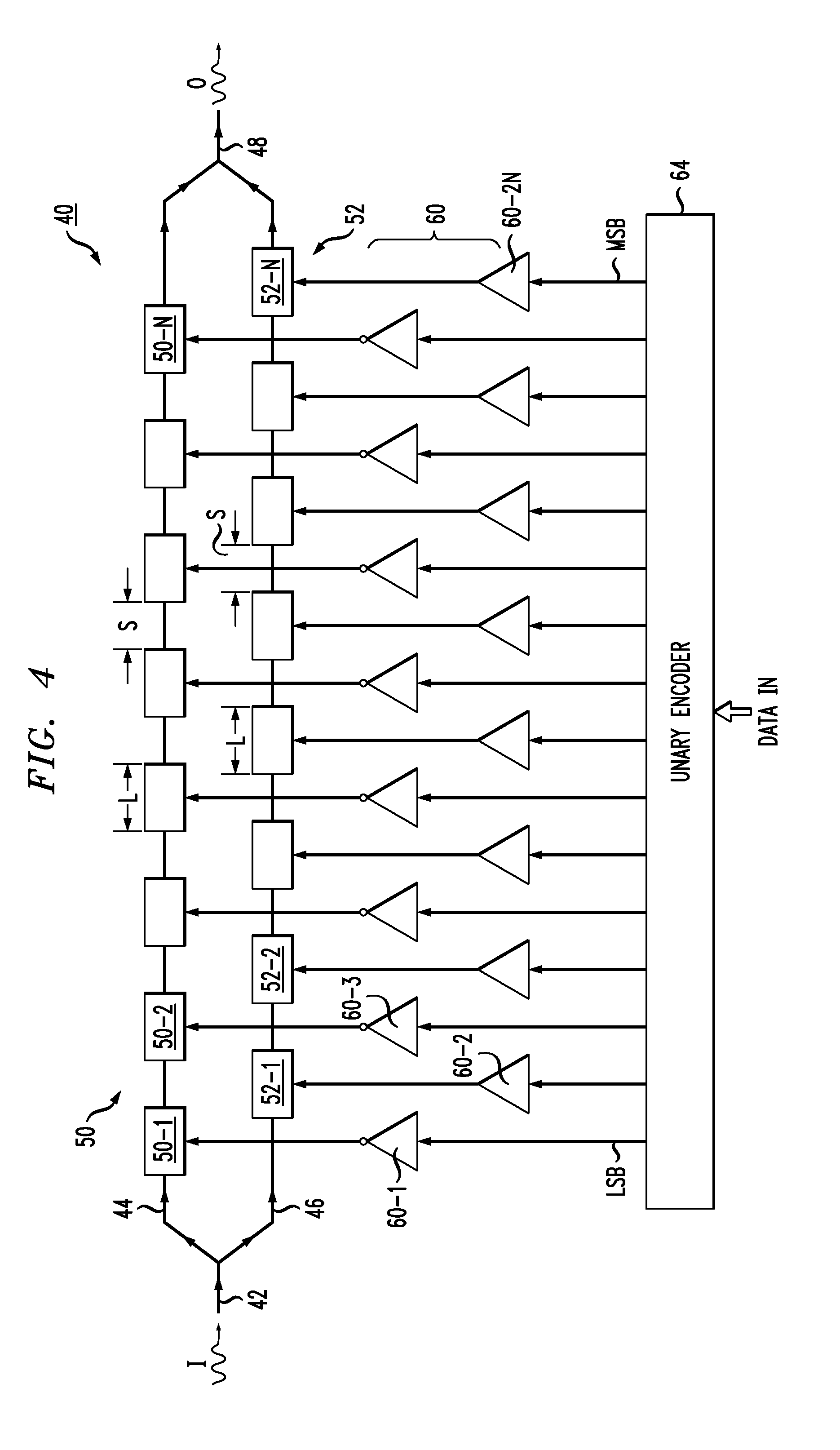
[0029]FIG. 4 illustrates an exemplary Mach Zehnder interferometer (MZI) 40 formed to utilize unary encoding in accordance with the present invention. As shown, MZI 40 comprises an input optical waveguide 42 for receiving an input signal I from an optical source (either a pulse or CW signal). Input waveguide 42 thereafter splits into a pair of parallel waveguide arms 44 and 46, with a portion of the input optical signal propagating along each waveguide arm. An output waveguide 48 is disposed to combine the output signals from the pair of parallel waveguide arms 44 and 46 to form a modulated optical output signal O.

[0030]MZI 40 further comprises a first plurality of N modulating sections 50 that are disposed along waveguide arm 44 and a second plurality of N modulating sections 52 are disposed along waveguide arm 46. As seen by reference to FIG. 4, each modulating section is of essentially the same length L and the inter-section spacing S is essentially the same as well. As mentioned ...


PUM

PropertyMeasurementUnit
phase shiftaaaaaaaaaa
lengthaaaaaaaaaa
refractive indexaaaaaaaaaa

Abstract

An optical modulator is configured to include multiple modulating sections formed along each arm and create a unary-encoded optical output signal by driving the number of sections required to represent the data value being transmitted (e.g., three sections driven to represent the data value “3”, four sections driven to represent the data value “4”). An auxiliary modulating section, isolated from the optical signal path, is included for creating a path for current flow in situations where only an odd number of modulating sections are required to represent the data. The activation of the auxiliary modulation section minimizes the current imbalance that would otherwise be present along a common node of the arrangement.

Description

CROSS REFERENCE TO RELATED APPLICATIONS[0001]This application claims the benefit of U.S. Provisional Application No. 61 / 450,497, filed Mar. 8, 2011 and herein incorporated by reference.TECHNICAL FIELD[0002]The present invention relates to optical modulators and, more particularly, to silicon-based optical modulators employing a unary encoding scheme with a multi-section modulator structure, including the use of an auxiliary modulator section to provide load balancing for all possible code patterns.BACKGROUND OF THE INVENTION[0003]For many years, external optical modulators have been made out of electro-optic material, such as lithium niobate. Optical waveguides are formed within the electro-optic material, with metal contact regions disposed on the surface of each waveguide arm. The application of a voltage to a metal contact will modify the refractive index of the waveguide region underneath the contact, thus changing the speed of propagation along the waveguide. By applying the vo...

Claims


Application Information

Patent Timeline
Patent Type & Authority Applications(United States)
IPC IPC(8): G02F1/035
CPCH04B10/5051G02F1/011G02F2001/0113H04B10/5053H04B10/516G02F1/225G02F1/0113
Inventor METZ, PETER C.DAMA, BIPINSHASTRI, KALPENDU
Owner CISCO TECH INC
Why Eureka
Try Eureka