
Semiconductor device manufacturing method

a manufacturing method and semiconductor technology, applied in the manufacture of printed circuits, solid-state devices, basic electric elements, etc., can solve the problems of crack formation in the sealant resin body “f”, vaporization and expansion of moisture absorbed in the package “p”, and higher costs, so as to achieve the effect of increasing manufacturing costs

Inactive Publication Date: 2012-09-13
TOYOTA JIDOSHA KK
View PDF3 Cites 18 Cited by
  • Summary
  • Abstract
  • Description
  • Claims
  • Application Information

AI Technical Summary

Benefits of technology

The present invention relates to a method for manufacturing a semiconductor device by joining a semiconductor package and a substrate using a solder layer. The technical effect of this invention is to provide a semiconductor device that is thinner and has improved heat dissipation capacity. The method involves exposing electrodes on the package and / or substrate, and joining them using a solder layer. The resulting semiconductor device has a heat dissipating pad exposed on one side of the sealant resin body, which is preferable for high-heat-generating semiconductor elements. The method also involves heating the package and substrate during reflow soldering, which can cause deformation of the semiconductor package. The deformation mode is observed as a roll-back of the electrodes against the substrate, which applies shear force or tensile force to the solder layer.

Problems solved by technology

An important technical challenge in the art is finding a way to realize a downsized (thinned) semiconductor package having improved heat dissipation capacity.
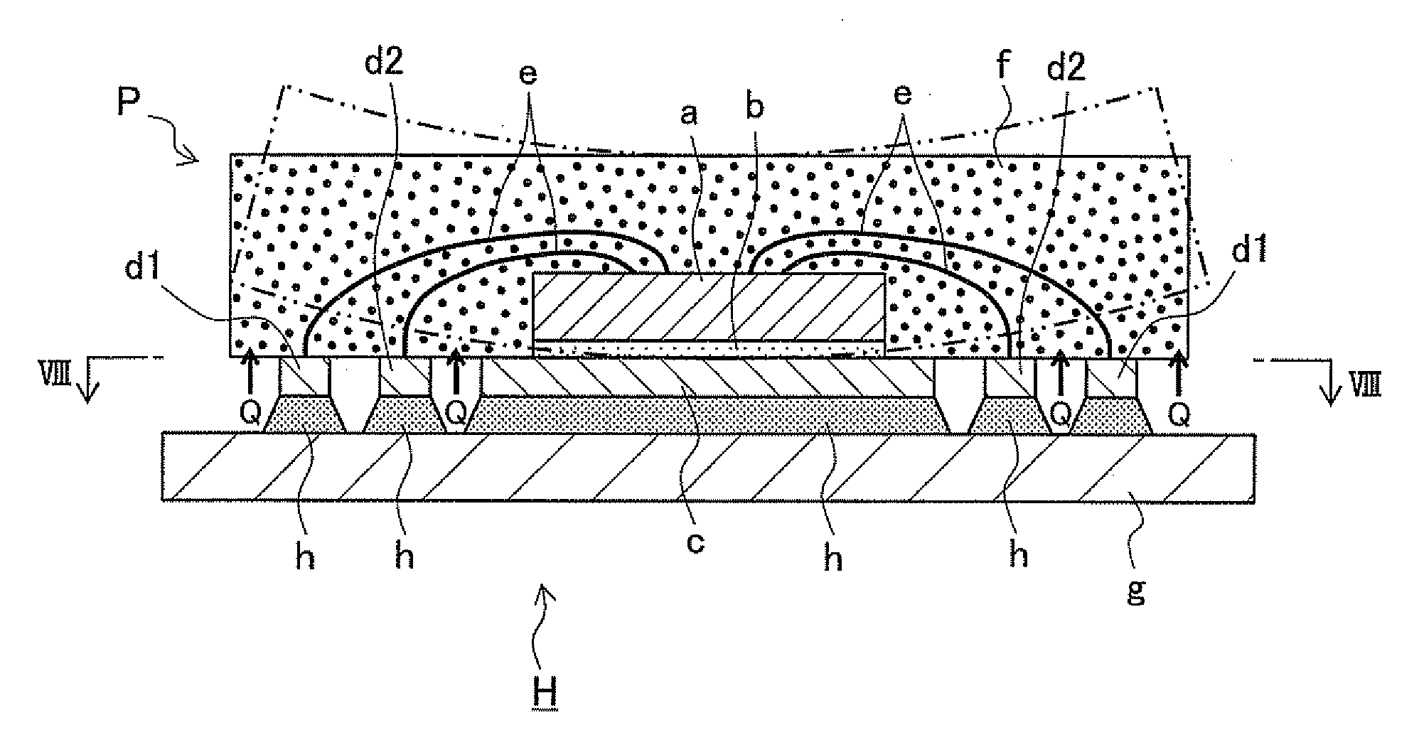
This results in vaporization and expansion of moisture absorbed in the package “P” during the period from assembly to mounting.
Also, detachment of the semiconductor element “a” from the heat dissipating pad “c” due to excessive deformation of the semiconductor package “P,” detachment of the heat dissipating pad “c” from the sealant resin body “f,” and crack formation in the sealant resin body “f” have been problematic.
However, it can be easily predicted that it will be difficult to manufacture a semiconductor package with a line-symmetric configuration along the line passing through the center of the thickness, and manufacturing of such semiconductor package will result in higher costs.
In addition, from a practical standpoint, it must be said that the general versatility of such vertically or horizontally symmetric semiconductor package is low.
Therefore, it is difficult to say that the use of such semiconductor package is a practical and effective way to solve the above problems in the art.

Method used


Image

  • Semiconductor device manufacturing method
  • Semiconductor device manufacturing method
  • Semiconductor device manufacturing method

Examples


Embodiment Construction

[0048]Embodiments of the present invention are described below with reference to the drawings. In addition, needless to say, the semiconductor device shown in each figure, the shapes of longitudinal sections of members constituting each device, the positions of semiconductor elements, electrodes, and the like are not limited to the examples in the drawings. Further, a semiconductor device may be accommodated in an exterior case.

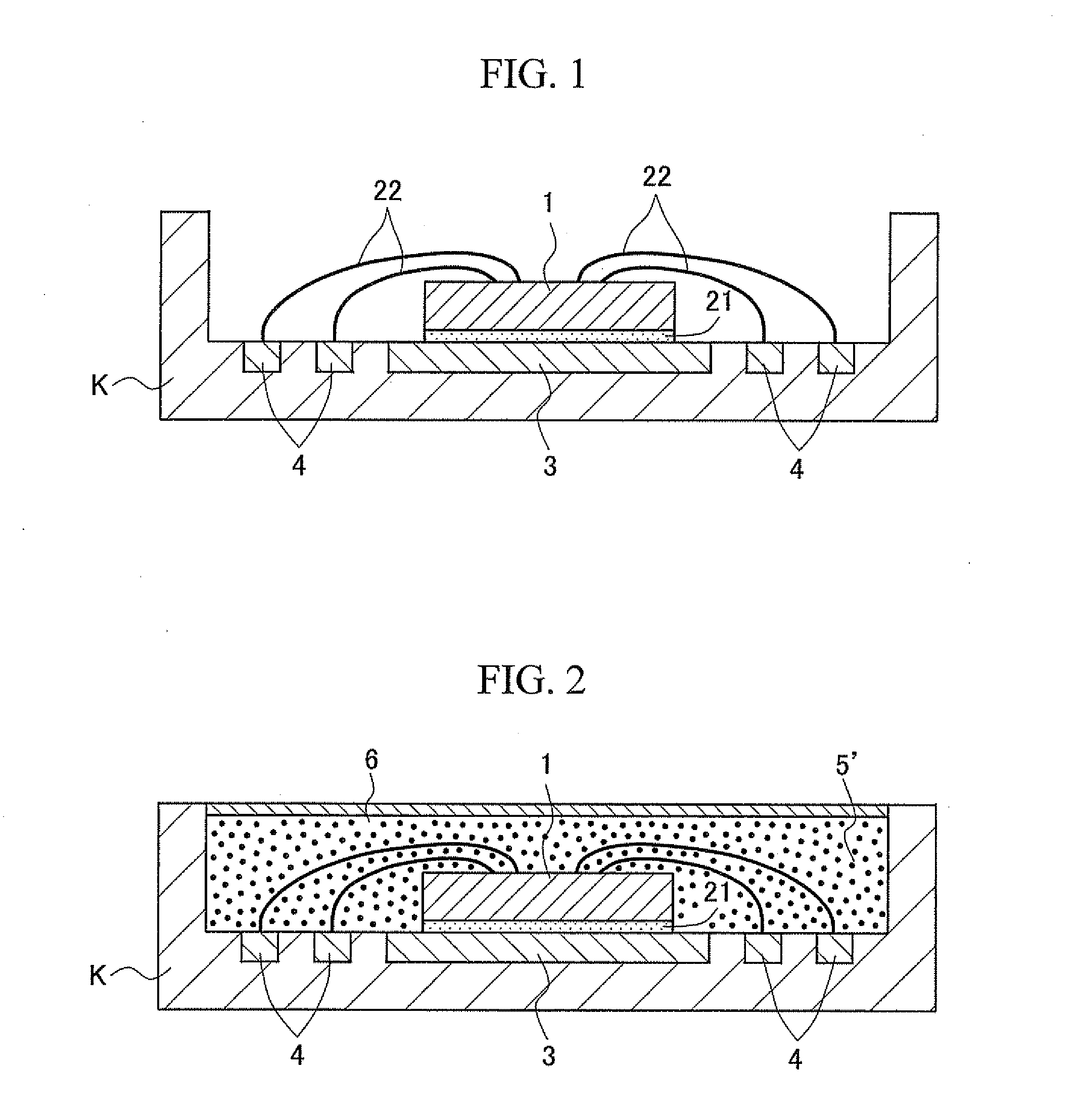
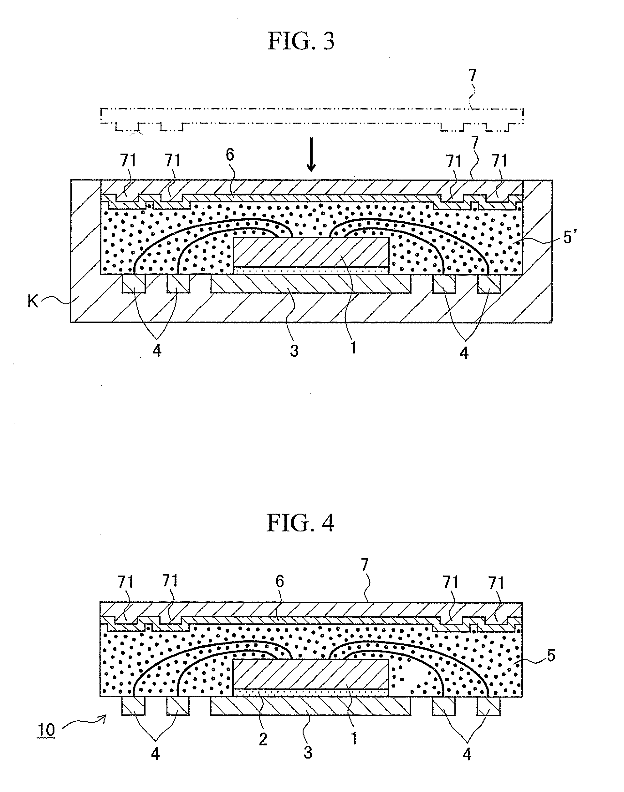
[0049]FIGS. 1 to 3 schematically illustrate the flow of the first step of the semiconductor device manufacturing method of the present invention. FIG. 4 schematically illustrates a semiconductor package intermediate manufactured in the first step. In addition, FIG. 5 schematically illustrates the second step of the semiconductor device manufacturing method of the present invention. FIG. 6 schematically illustrates the third step of the semiconductor device manufacturing method of the present invention and one embodiment of a semiconductor device manufactured ...


PUM


Abstract

A method for manufacturing a semiconductor device includes: a step of producing a semiconductor package intermediate by injecting a resin into a forming die in which electrodes, a heat dissipating pad, and a semiconductor element are disposed, providing a peel-off film on one side of the resin in the form of a still-uncured resin body opposite from the other side facing the heat dissipating pad and a rigid material on one side of the peel-off film, and curing the uncured resin body to form a sealant resin body; a step of forming a solder layer by reflow soldering between a substrate and the intermediate; and a step of removing the rigid material from the peel-off film, wherein the rigid material is integrated into the intermediate so as to make the thermal expansion coefficient and rigidity of the intermediate approximately equal to those of the substrate.

Description

TECHNICAL FIELD[0001]The present invention relates to a method for manufacturing a semiconductor device by joining a semiconductor package and a substrate via a solder layer.BACKGROUND ART[0002]Along with the development of smaller, multifunctional, high-performance electronic devices in recent years, demands have emerged for advanced high-density packaging of semiconductor parts. An important technical challenge in the art is finding a way to realize a downsized (thinned) semiconductor package having improved heat dissipation capacity. Examples of such semiconductor package types include the CSP (Chip Size Package), the BGA (Ball Grid Array) package, the LGA (Land Grid Array) package, the MCP (Multi Chip Package), and the SiP (System in Package).[0003]Regarding semiconductor package downsizing (thinning), there is a leadless-type semiconductor package available on the market that is obtained by partially exposing electrode terminals on the package bottom or side faces without seali...

Claims


Application Information

Patent Timeline
Patent Type & Authority Applications(United States)
IPC IPC(8): H01L21/56H01L21/60
CPCH01L21/565H01L2924/1815H01L23/3107H01L23/562H01L2224/48247H01L2924/01004H01L2924/09701H05K3/3421H01L2224/48091H01L2224/73265H01L2924/3511H01L21/568H01L2924/10253H01L2924/01019H01L24/48H01L2924/00H01L2924/00014H01L2224/32245H01L24/73H01L2924/181H01L2924/14H01L2924/00012H01L2224/45099H01L2224/45015H01L2924/207
Inventor KAWAHARA, NAKAYA
Owner TOYOTA JIDOSHA KK
Learn More