
Directed energy weapon deployment simulation

a technology of directed energy and simulation, applied in the direction of instruments, cad techniques, using reradiation, etc., can solve the problem of significant threat of terrorist attacks on civilian aircra

Active Publication Date: 2012-09-13
RAYTHEON CO
View PDF4 Cites 22 Cited by
  • Summary
  • Abstract
  • Description
  • Claims
  • Application Information

AI Technical Summary

Problems solved by technology

However, MANPADS missiles are now widely available and are considered a significant threat for terrorist attacks against civilian aircraft.

Method used


Image

  • Directed energy weapon deployment simulation
  • Directed energy weapon deployment simulation
  • Directed energy weapon deployment simulation

Examples


Embodiment Construction

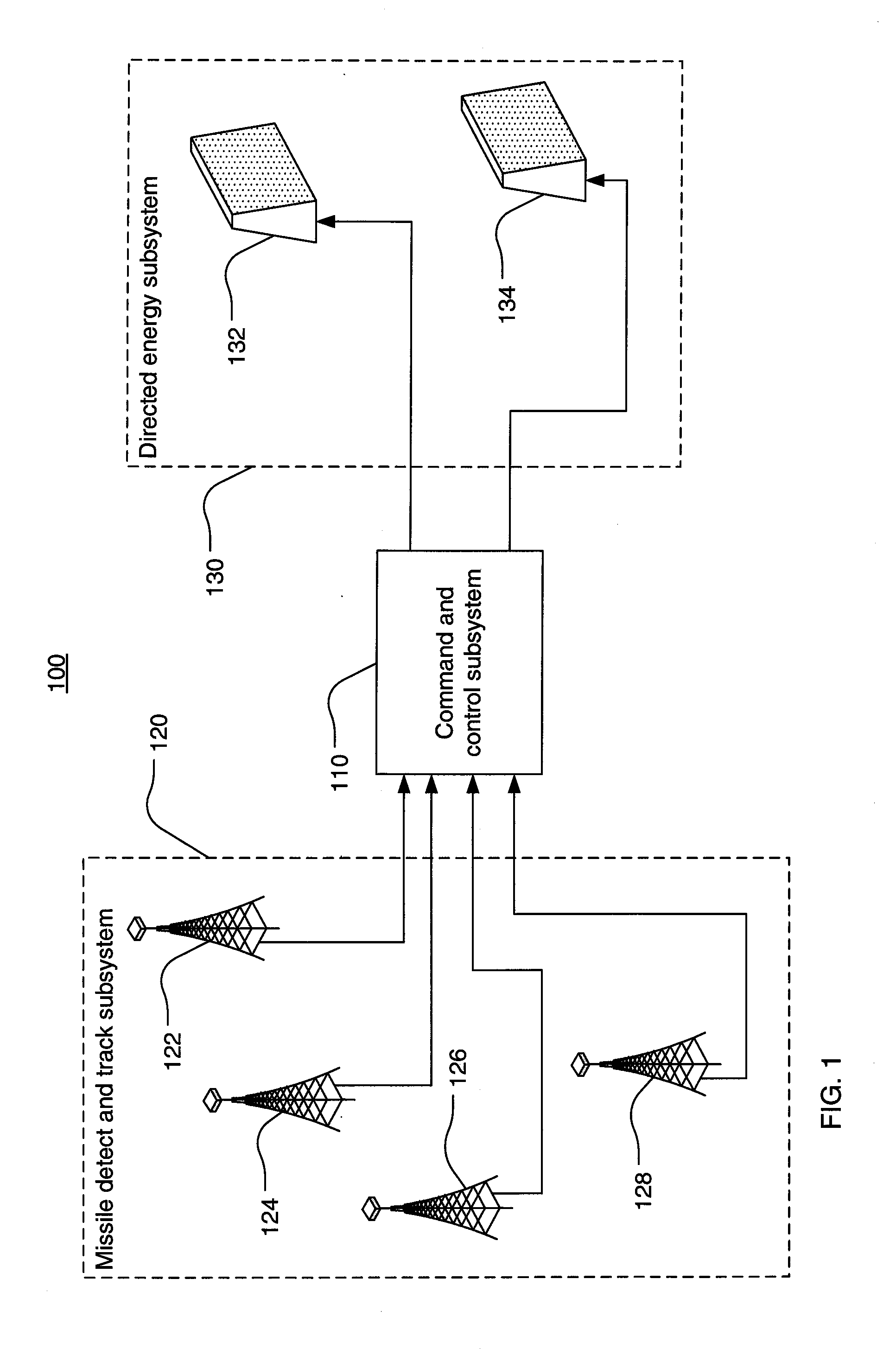
[0019]Referring now to FIG. 1, an exemplary counter-MANPADS directed energy weapon (DEW) system 100 may include a missile detect and track (MDT) subsystem 120, a command and control (C2) subsystem 110, and a directed energy subsystem 130. The directed energy subsystem 130, as illustrated in the example of FIG. 1, may be a high power microwave subsystem. Within this description, a MANPAD missile will be referred to as the threat, and an aircraft under attack by the MANPAD threat will be referred to as the target. The DEW system 100 may be designed to protect targets from threats within a volume of space, herein termed the “protected volume”, which may include all anticipated target locations. The protected volume may include, for example, the region surrounding the ingress and egress routes from an airport from ground level to an altitude of 20,000 feet.

[0020]The MDT subsystem 120 may include a plurality of passive sensors. While FIG. 1 shows four passive sensors 122-128, an actual d...


PUM


Abstract

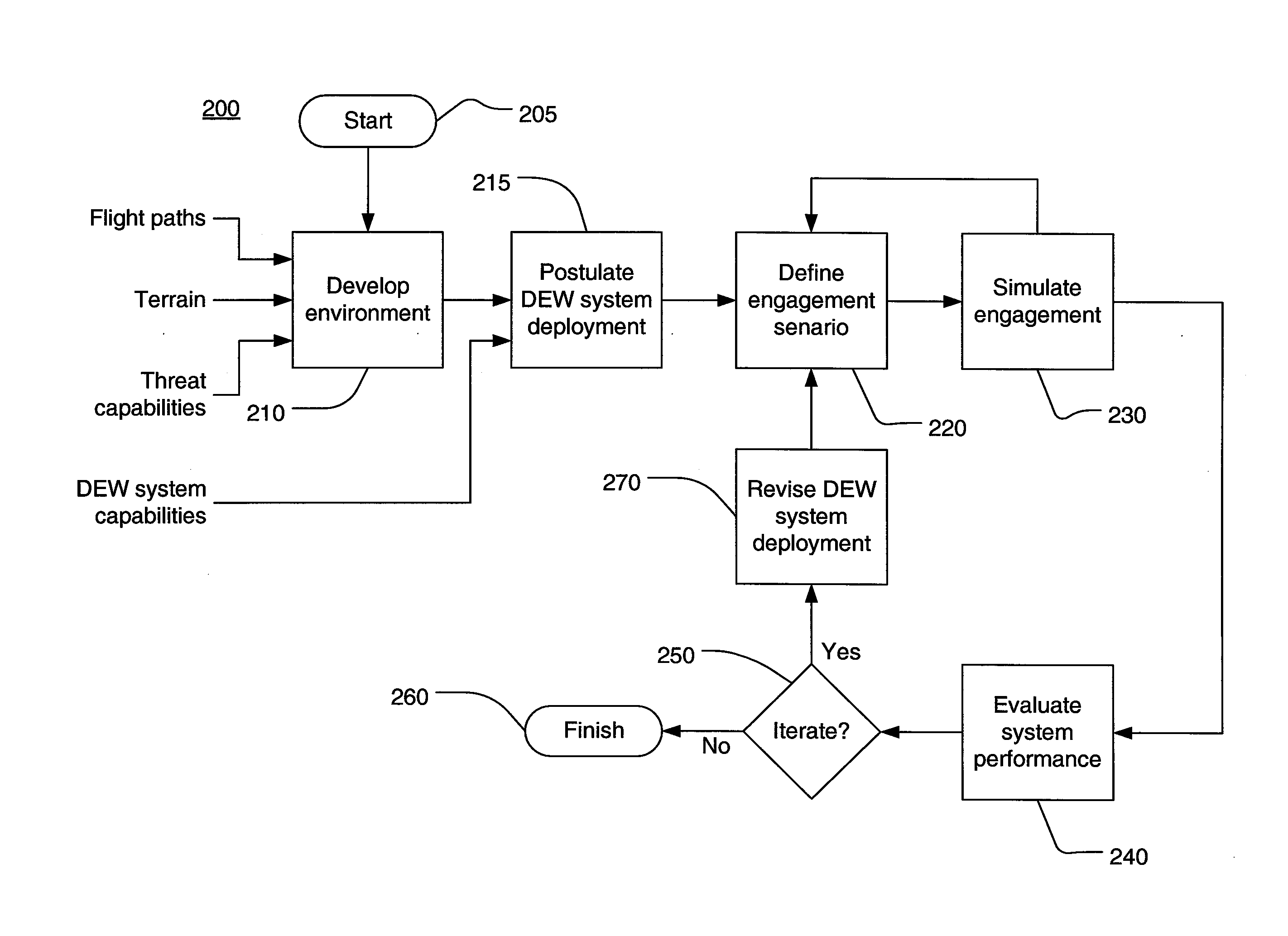
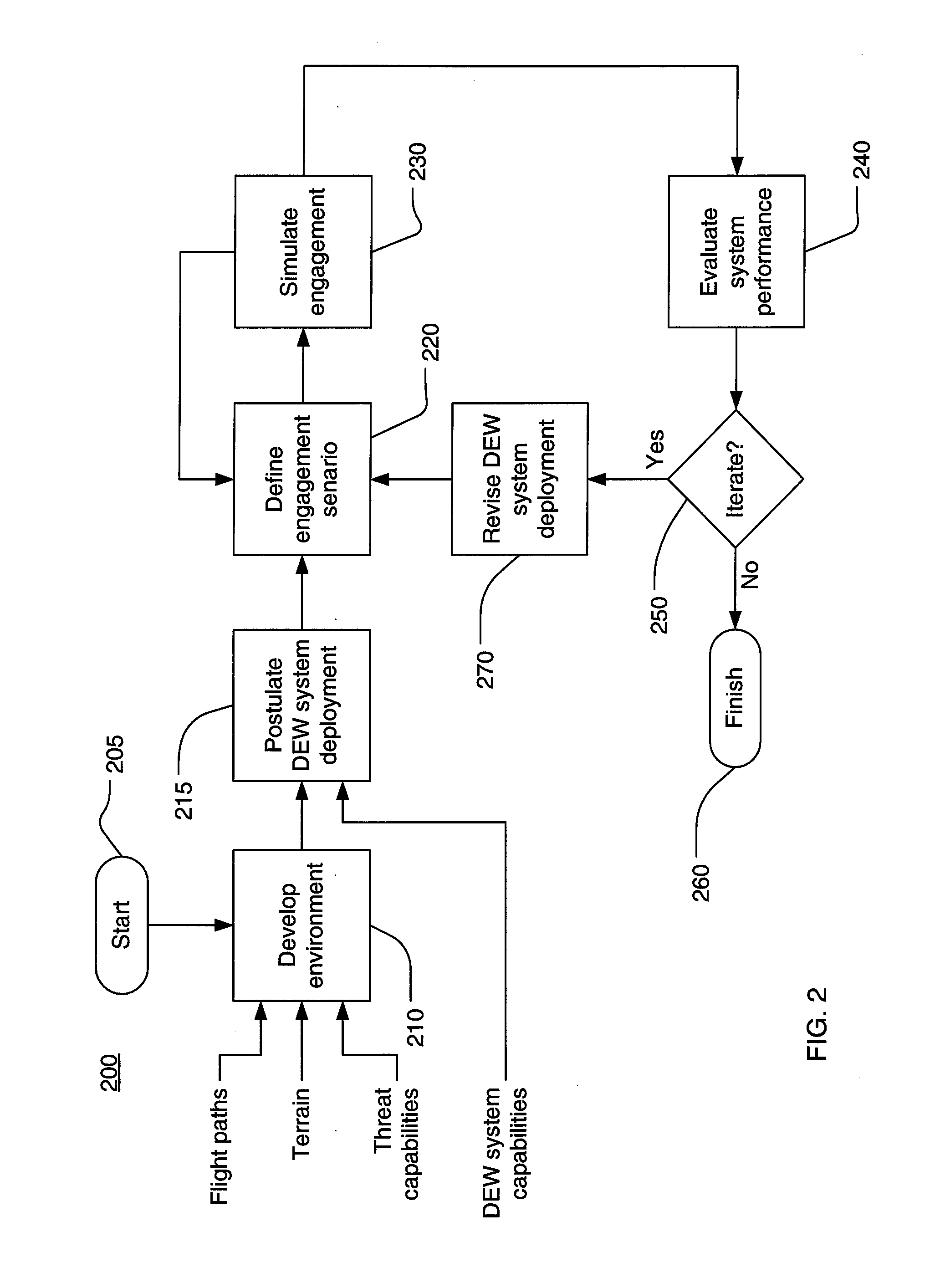
Methods, apparatus, and computer readable media for designing an effective and efficient directed energy weapon system. A method for designing a directed energy weapons system may include modeling an environment and postulating a directed energy weapons system deployment. The capability of the postulated directed energy weapon system deployment to defend a target aircraft against a missile threat within the environment may then be simulated. The postulated directed energy weapon system deployment may be iteratively improved based on simulation results.

Description

RELATED APPLICATION INFORMATION[0001]This application claims benefit under 35 U.S.C. §119(e) of the filing date of provisional patent application Ser. No. 60 / 940,268, filed May 25, 2007, entitled VIGILANT EAGLE DEPLOYMENT SIMULATION. This application is related to application Ser. No. 11 / 940,425, filed Nov. 15, 2007, entitled System and Method for Diverting a Guided Missile; Ser. No. 11 / 423 / 520, filed Jun. 12, 2006, entitled Anti-Missile System and Method; Ser. No. 11 / 875,131, filed Oct. 19, 2007, entitled RF Waveform Modulation Apparatus and Method; and Ser. No. 11 / 821,760, filed Jun. 24, 2007, entitled High Power Phased Array antenna System and Method with Low Power Switching.NOTICE OF COPYRIGHTS AND TRADE DRESS[0002]A portion of the disclosure of this patent document contains material which is subject to copyright protection. This patent document may show and / or describe matter which is or may become trade dress of the owner. The copyright and trade dress owner has no objection t...

Claims


Application Information

Patent Timeline
IPC IPC(8): G06G7/48
CPCF41H13/0043G06F2217/16G06F17/5009G06F2111/10G06F30/20
Inventor AHRENS, FREDERICK A.MCMASTER, DANIEL L.
Owner RAYTHEON CO
Learn More