Force/moment sensor for measurment of forces and moments

a force/moment sensor and moment sensor technology, applied in the field of force/moment sensors, can solve the problems of inability to miniaturize such a force/moment sensor to an outer diameter of less than 20 mm, high manufacturing cost, and inability to meet the requirements of measurement, etc., to achieve accurate orientation of individual deformation transducers relative to each other, and accurate arrangement of deformation transducers

Active Publication Date: 2012-09-20
DEUTSCHES ZENTRUM FUER LUFT & RAUMFAHRT EV
View PDF5 Cites 16 Cited by
  • Summary
  • Abstract
  • Description
  • Claims
  • Application Information

AI Technical Summary

Benefits of technology

[0021]A further advantage of the force/moment sensor of the invention in a preferred embodiment thereof resides in that some, and preferably all, of the deformation transducers can be realized as film-type strain gauges. In this case, individual ones or all of t

Problems solved by technology

Such a force/moment sensor, however, has the disadvantage that the manufacture as a monolithic component is extremely complex and thus expensive.
Further, such a force/moment sensor has a large size particularly in the axial direction so that the range of applications of such a force/moment sensor is restricted.
For this reason, a miniaturization of such a force/moment sensor to an outer diameter of less than 20 mm is not possible, particularly because of the need to provide sufficient mounting space for the strain gauge arranged laterally on th

Method used


Image

  • Force/moment sensor for measurment of forces and moments
  • Force/moment sensor for measurment of forces and moments
  • Force/moment sensor for measurment of forces and moments

Examples


Embodiment Construction

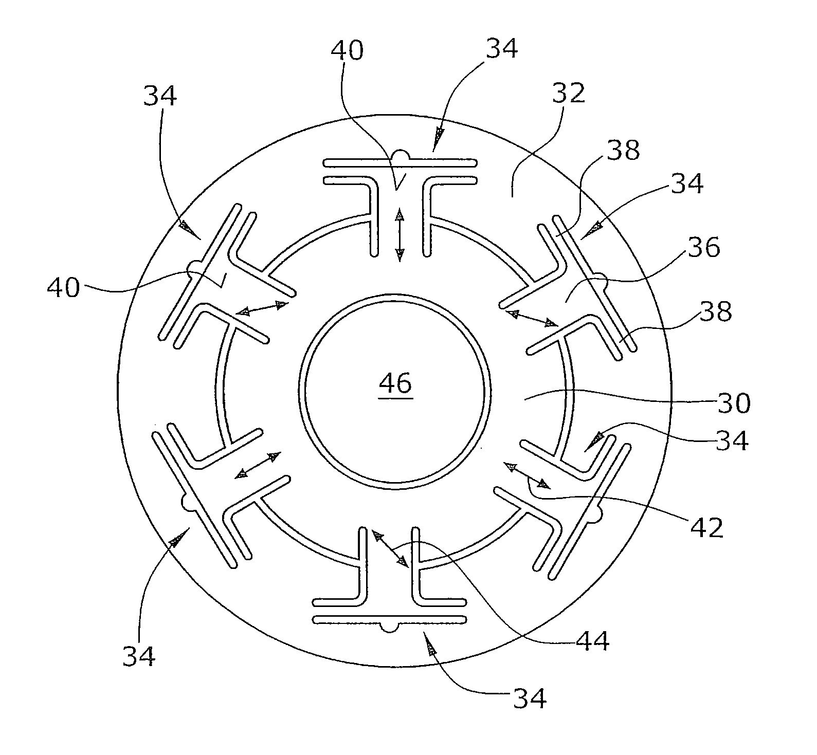
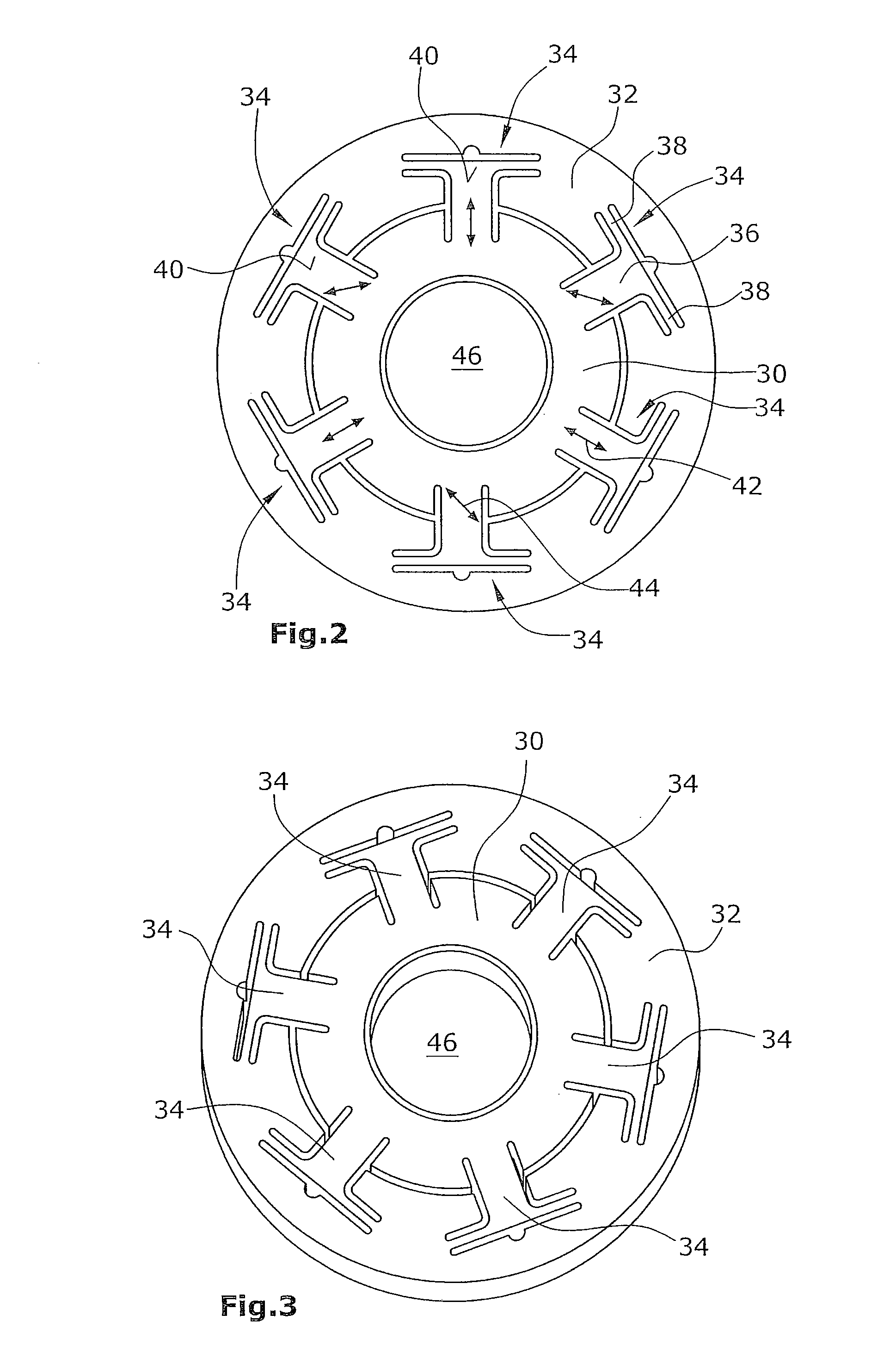
[0026]The force / moment sensor according to the invention (FIGS. 2 and 3) comprises, in its illustrated preferred embodiment, a substantially circular inner holding element 30 which is surrounded by an outer holding element 32 being also substantially circular. The two holding elements 30,32 are connected to each other via six deformation elements 34 arranged with a regular distribution on the periphery of the inner holding element 30. When seen in plan view, the individual deformation elements 34 (FIG. 2) are T-shaped. The identically shaped deformation elements 34 comprise a deformation bar 36 and two connection webs 38 connected to deformation bar 36. Relative to the circular inner holding element 30, deformation bar 36 is arranged radially, with the two connection webs 38 extending tangentially. On its inward end, the deformation bar 36 is connected to the inner holding element 30. The two connection webs 38 are by their outer ends connected to the outer holding element 32.

[0027]...


PUM


Abstract

A force/moment sensor for measurement of three orthogonal forces and three orthogonal moments, comprises an inner holding element which is surrounded by an outer holding element. The two holding elements are connected to each other by deformation elements. For each deformation element, at least one deformation transducer is provided. The force/moment sensor is preferably monolithic, and the deformation transducers, formed as strain gauges, are preferably arranged in one plane or in two preferably parallel planes.

Description

BACKGROUND OF THE INVENTION[0001]1. Field of the Invention[0002]The present invention relates to a force / moment sensor for measurement of particularly three orthogonal forces and three orthogonal moments.[0003]2. Description of the Prior Art[0004]For measurement of three forces and three moments, a monolithic force / moment sensor is known from DE 102 17 018. This known sensor comprises two circular cylindrical rings arranged at an axial distance from each other. The two rings are connected to each other via six rods of identical length which are distributed along the periphery at uniform intervals. On said rods, strain gauges are arranged. With the aid of the strain gauges, three orthogonal forces and three orthogonal moments can be determined. The connection between the six rods and the two circular cylindrical rings is realized respectively via flexure hinges. The strain gauges are connected via electric lines to an evaluation unit for determining the forces and moments. Such a for...

Claims


Application Information

Patent Timeline
IPC IPC(8): G01L1/22G01L1/00
CPCG01L5/161G01L5/1627
Inventor SEIBOLD, ULRICH
Owner DEUTSCHES ZENTRUM FUER LUFT & RAUMFAHRT EV
Why Eureka
Try Eureka