

Acoustic treatment vessel and method for acoustic treatment
a treatment vessel and acoustic energy technology, applied in the direction of instruments, ultrasonic/sonic/infrasonic diagnostics, etc., can solve the problems of inability to control the efficiency of sonic energy, the inability to accurately process materials, and the inability to achieve precise materials processing or reaction control mechanisms, etc., to achieve the effect of improving the efficiency of systems and methods for processing samples using focused acoustic and improving the efficiency of processing samples
- Summary
- Abstract
- Description
- Claims
- Application Information
AI Technical Summary
Benefits of technology
Problems solved by technology
Method used
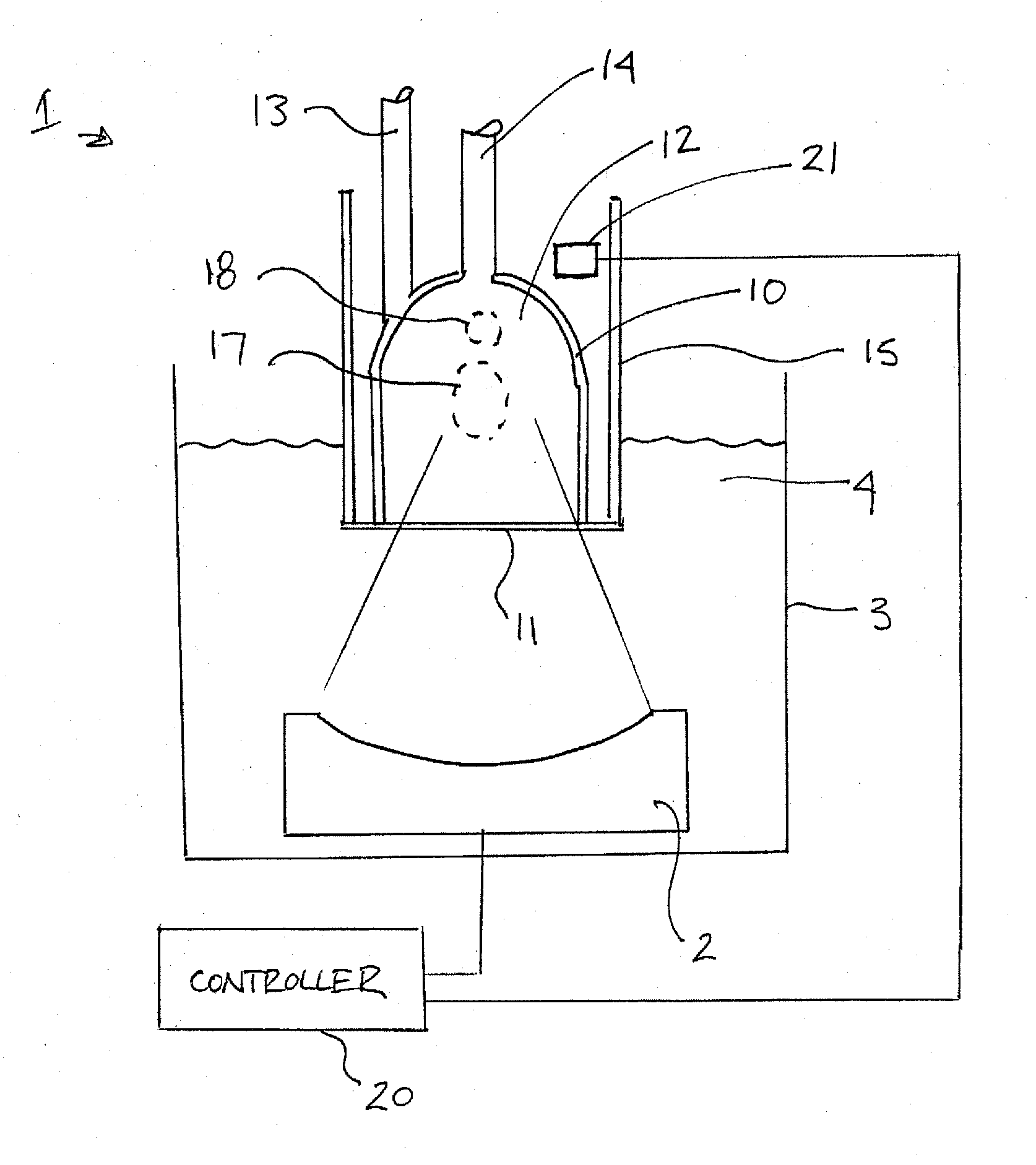
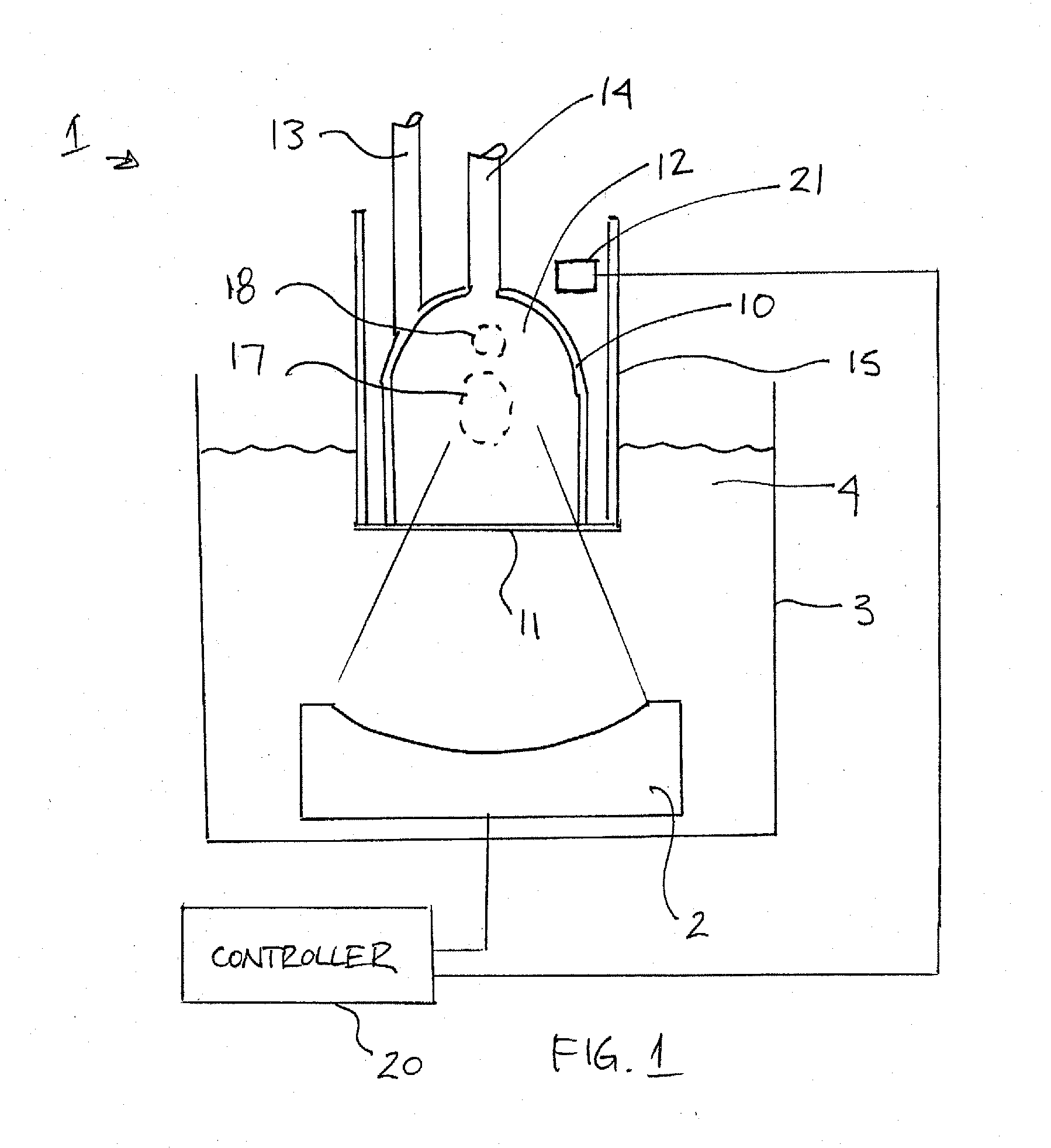
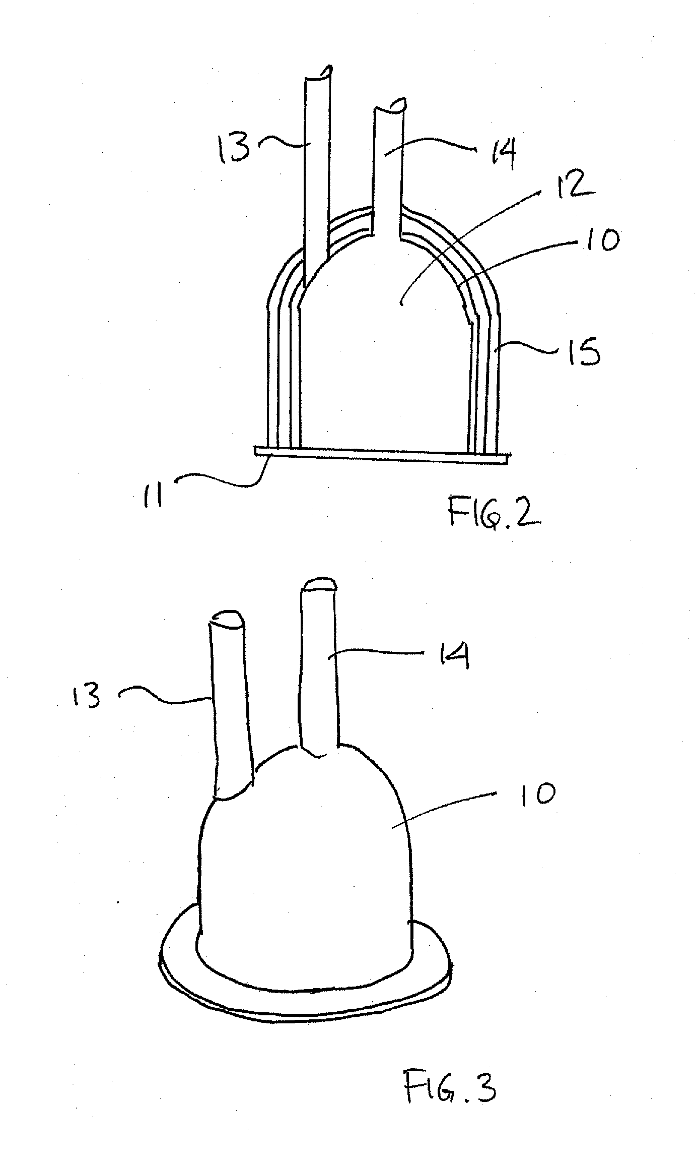
Image

Examples
example
[0152]The following example is intended to illustrate certain embodiments of the present invention, but is not to be construed as limiting and do not exemplify the full scope of the invention.
[0153]A first single-use consumable apparatus having a cylindrical chamber similar to that shown above in FIG. 11 was manufactured. The depth D was approximately 3 mm and the width W was approximately 11 mm, giving rise to an internal volume 58 of the chamber of approximately 300 μL. The upper wall 52 of the chamber was composed of a thin layer of glass less than 1 mm thick with air located on the opposite side of the glass. The inner surface of the upper wall defining the internal volume of the chamber was substantially flat. The side wall 54 of the chamber comprised aluminum. The internal volume 58 of the chamber was sealed by a window 56 comprising KAPTON.
[0154]A second single-use consumable apparatus having a cylindrical chamber similar to that shown above in FIG. 12 was also manufactured. ...
PUM
 Abstract
Description
Claims
Application Information