Device and method for feeding metal material into a melting plant

a technology of metal material and melting plant, which is applied in the direction of furnace components, lighting and heating apparatus, furnace types, etc., can solve the problems of not providing any type of continuous loading with vibrating conveyor, complicated melting cycle, etc., and achieves better filling, better distribution, and improved metal material distribution

Active Publication Date: 2012-09-20
DANIELI & C OFF MEC SPA
View PDF3 Cites 5 Cited by
  • Summary
  • Abstract
  • Description
  • Claims
  • Application Information

AI Technical Summary

Benefits of technology

[0039]In a further solution of the invention, an oscillation movement of the hearth of the furnace is associated with an advance of the loading plane of the connection conveyor, in order to further improve the distribution of the metal material unloaded onto the bottom of the hearth of the furnace.
[0040]In another solution of the invention, for the first charge of the furnace as described above, shredded or fragmented scrap is used, with the advantage that it guarantees a better filling and a better distribution on the bottom surface of the furnace, and also makes it melt quicker at the moment the furnace is switched on.
[0041]In yet another solution of the invention, for the first charge and/or continuous charge, coal and/or other specific additives are used, either by itself or mixed with the metal material. The coal, for example, has the function of carburizing the bath of liquid metal and to quickly form a foamy slag which, covering the electric arc, protects the refractory of the hearth from the action of the arc itself This allows to increase the operative length of the refractory in efficient operating conditions.
[0042]In a further solution of the invention, the fu...

Problems solved by technology

The use of a basket to carry out the first charge, although on the one hand it satisfies this need, on the other hand it makes the whole melting cycle more complex, in that it requires the use of specific equipment, such as the basket, the filling systems, the transport systems, a suitable storage zone etc., which are used for only a small fraction of the cycle, remaining idle for the rest of the melting cycle.
This solution therefore provides ...

Method used


Image

  • Device and method for feeding metal material into a melting plant
  • Device and method for feeding metal material into a melting plant
  • Device and method for feeding metal material into a melting plant

Examples


Embodiment Construction

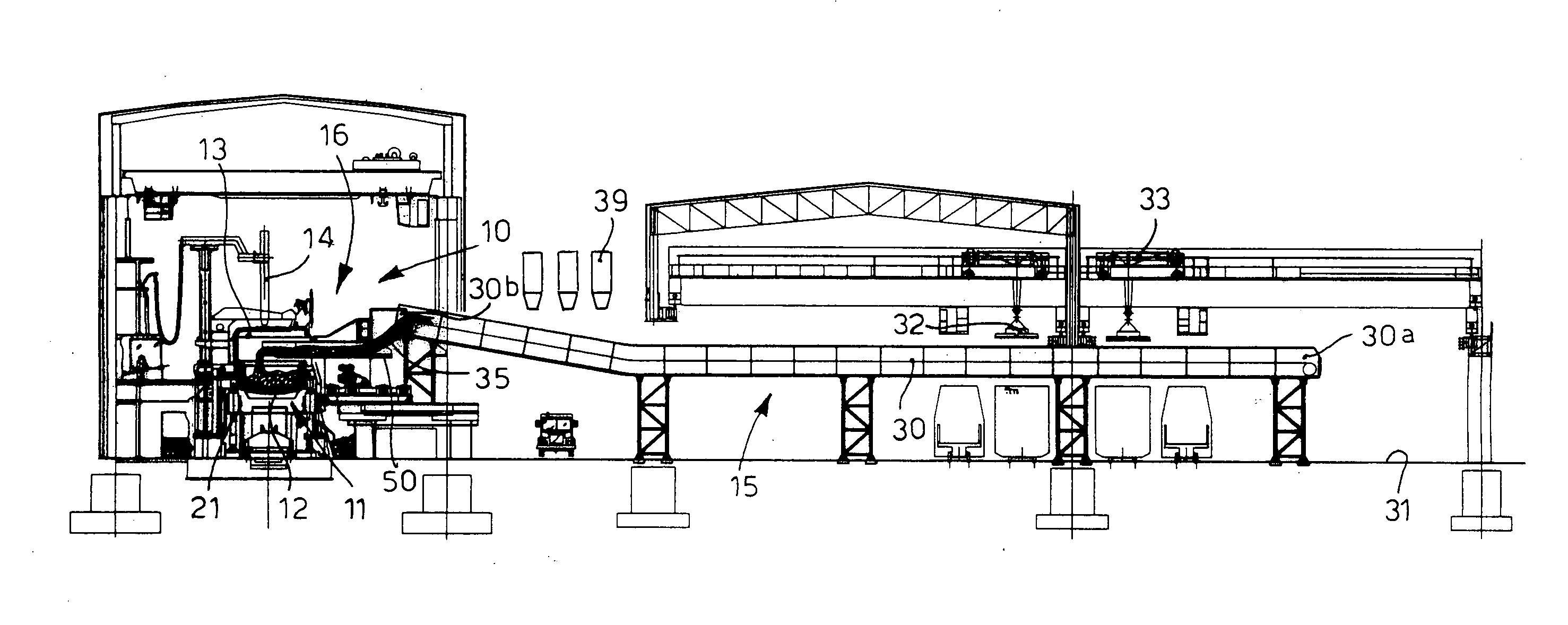
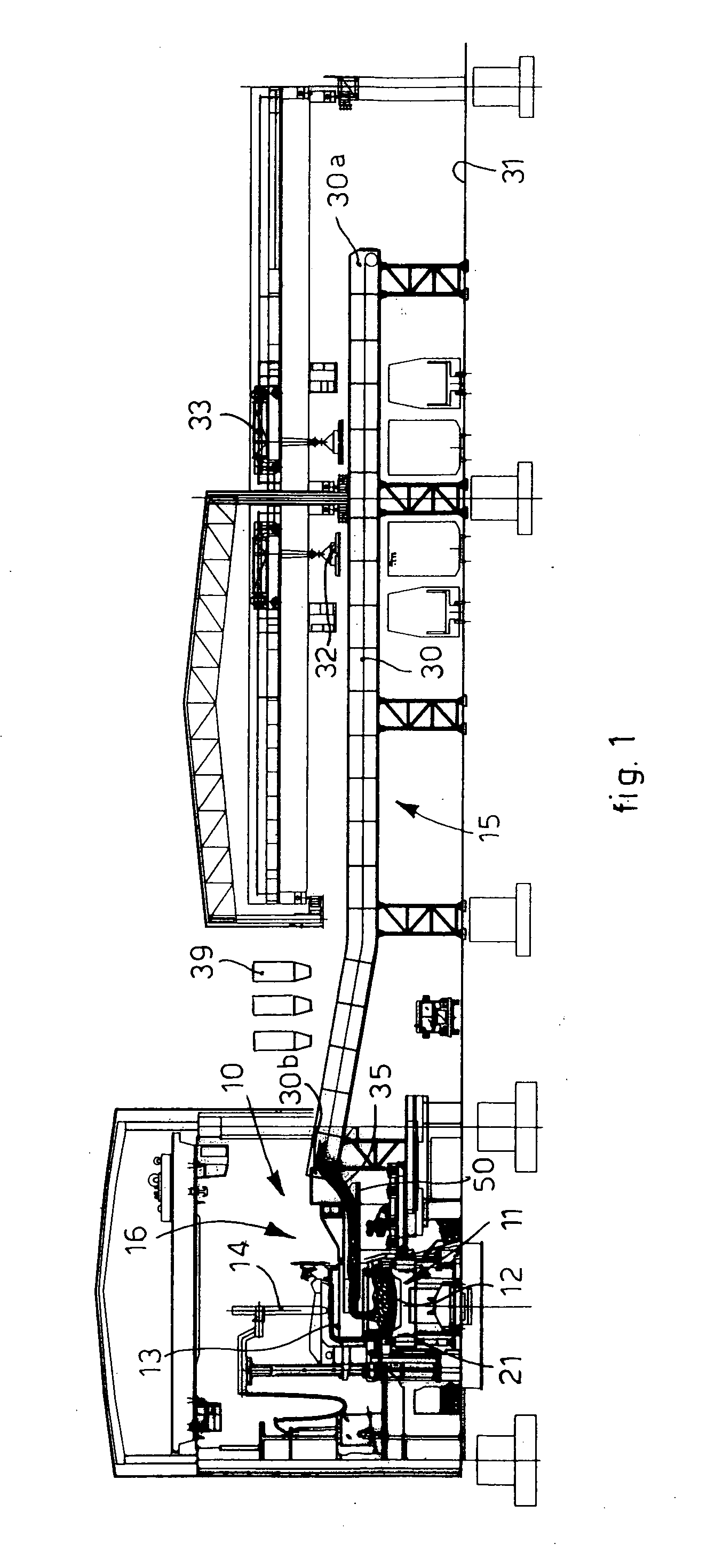
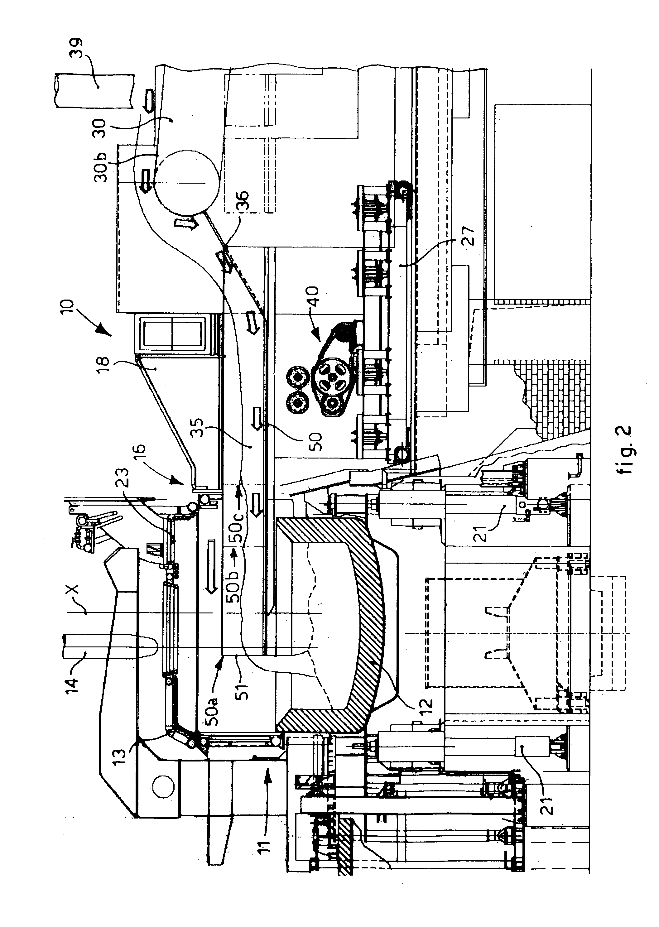
[0053]With reference to the attached drawings, the number 10 denotes in its entirety a device to feed a metal charge, denoted generally by the reference number 35, into an electric arc melting furnace 11, comprising a hearth 12 and a roof 13.

[0054]The feed device 10 consists of a main conveyor 15, which in the case of FIG. 1, simply to give an example, consists of a slatted belt 30 which has the advantage, thanks to its great strength, of being able to receive the charge material directly from orange peel grapples, spider grapples or magnets 32, moved by gantries 33 as seen in the drawing.

[0055]Other types of continuous conveyor belt come within the field of the present invention, hereafter called simply “belt”, such as for example a flexible belt made of steel or of rubber with a steel core, or a rigid belt with step-wise movement, or a track, or any other analogous or similar solution.

[0056]The main conveyor 15 is associated at the front with a connection conveyor 16, which determ...


PUM

PropertyMeasurementUnit
Flexibilityaaaaaaaaaa

Abstract

Device for feeding metal into melting plant, in particular into melting furnace including hearth and lateral aperture. Device includes means to feed metal terminally associated with a connection conveyor including a loading plane and cooperating with translation and positioning means. Connection conveyor able to assume first position during continuous loading step, wherein its front terminal end is located substantially flush with the furnace internal wall through the aperture, to introduce metal inside the furnace; a second position distanced from the furnace wall during the step of tapping liquid metal from the furnace; and a third position while first loading the furnace, with the furnace switched off, wherein its loading plane front end is inside the furnace volume to be disposed in proximity to the distal internal wall opposite the furnace proximal internal wall, to unload and distribute a charge to cover at least part of the furnace bottom surface.

Description

FIELD OF THE INVENTION[0001]The present invention concerns a device and a method to feed metal material into a melting plant, particularly into an electric arc melting furnace, of the type which uses a loading system with introduction of the charge from one side of the furnace.[0002]In particular, the invention concerns the use of an introduction element to introduce the metal material having at least a loading plane which is selectively mobile, in order to be inserted into the melting furnace, during the first step when the melting cycle is started with the furnace switched off, in order to unload into the furnace a desired quantity of metal and / or non metal material which makes up the first charge of the furnace.BACKGROUND OF THE INVENTION[0003]Transformation and melting plants for metal charges are known, of the continuous charge type, which comprise an electric arc furnace suitable to collaborate with transport means of the linear conveyor type. The electric furnace provides at ...

Claims


Application Information

Patent Timeline
IPC IPC(8): B65G47/42B65G15/48B65G11/14B65G35/00B65G27/00
CPCF27B3/186F27B3/06C21C7/0025C21C2300/02C21C5/527F27D3/10Y02P10/20
Inventor BENEDETTI, GIANPIETROPOLONI, ALFREDO
Owner DANIELI & C OFF MEC SPA
Why Eureka
Try Eureka