
Laser scribing with extended depth affectation into a workplace

a technology of scribing and workpieces, applied in the field of laser machining, can solve the problems of epi damage and light loss, narrower streets between devices, and significant debris generation

Inactive Publication Date: 2012-09-20
IPG PHOTONICS CORP
View PDF11 Cites 172 Cited by
  • Summary
  • Abstract
  • Description
  • Claims
  • Application Information

AI Technical Summary

Problems solved by technology

Positioning the devices more closely on the semiconductor wafer results in narrower streets between the devices.
Although these techniques have been effective, there have also been drawbacks.
Both processes often cause significant debris generation and often require coating and rinsing processes to eliminate or reduce debris.
Back side scribing often uses a wider kerf and wider heat affected zone (HAZ) resulting in heat generation that may cause epi damage and light loss.
In particular, stealth scribing may limit the thickness of the wafer, may be difficult on warped wafers, and may be much slower on thicker wafers because several passes may be required to cause separation.
Stealth scribing techniques also present problems when machining wafers with DBR or metal reflector films because of the inability to obtain the desired focus inside of the wafer.
Stealth scribing also requires expensive lenses and tight focus tolerances and stealth scribing equipment generally has higher equipment costs and annual maintenance costs.

Method used


Image

  • Laser scribing with extended depth affectation into a workplace
  • Laser scribing with extended depth affectation into a workplace
  • Laser scribing with extended depth affectation into a workplace

Examples


Embodiment Construction

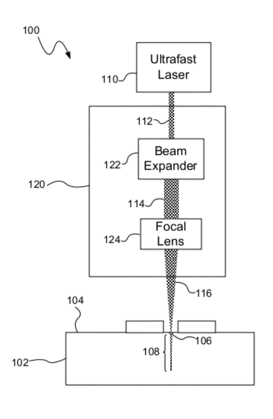
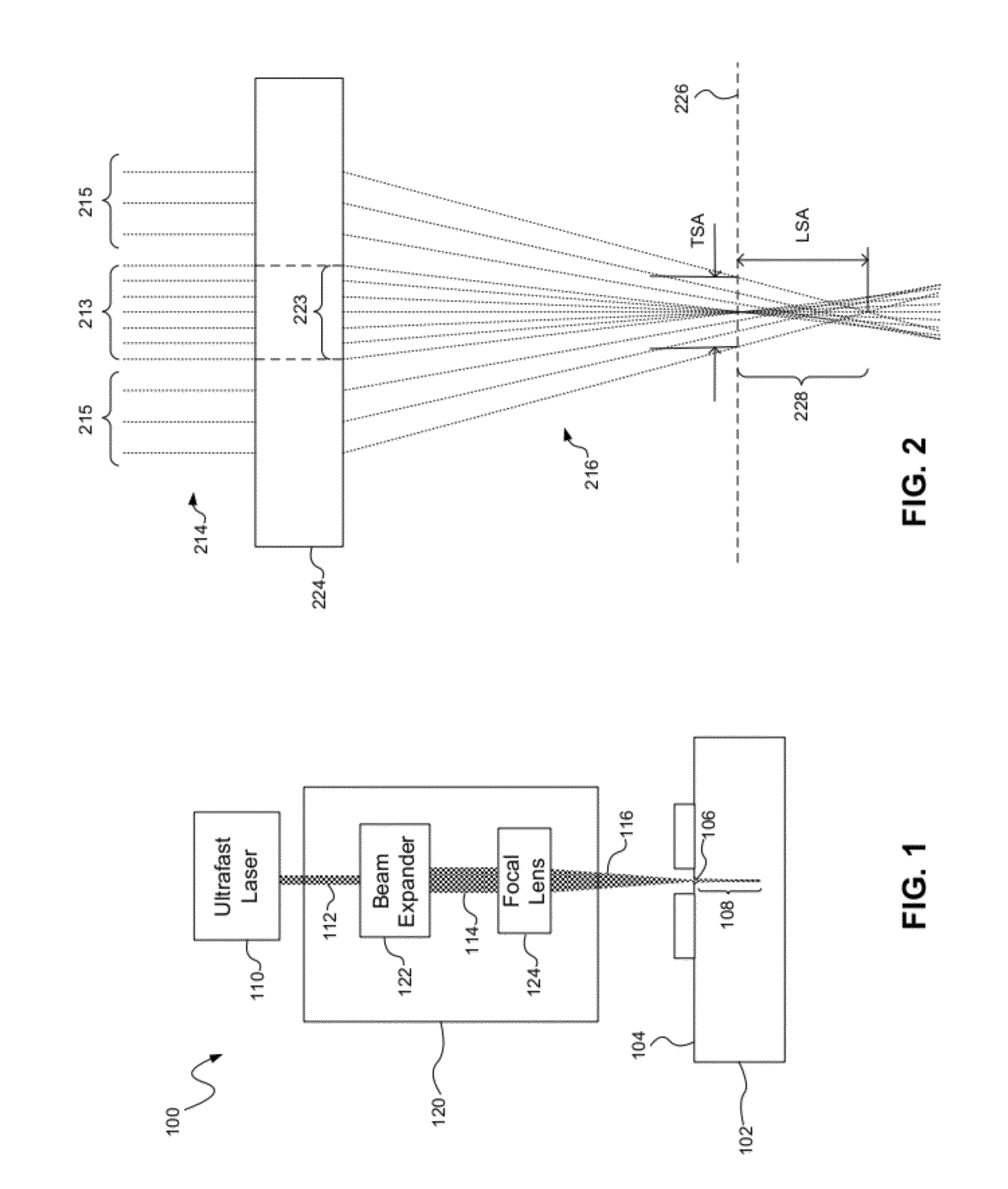
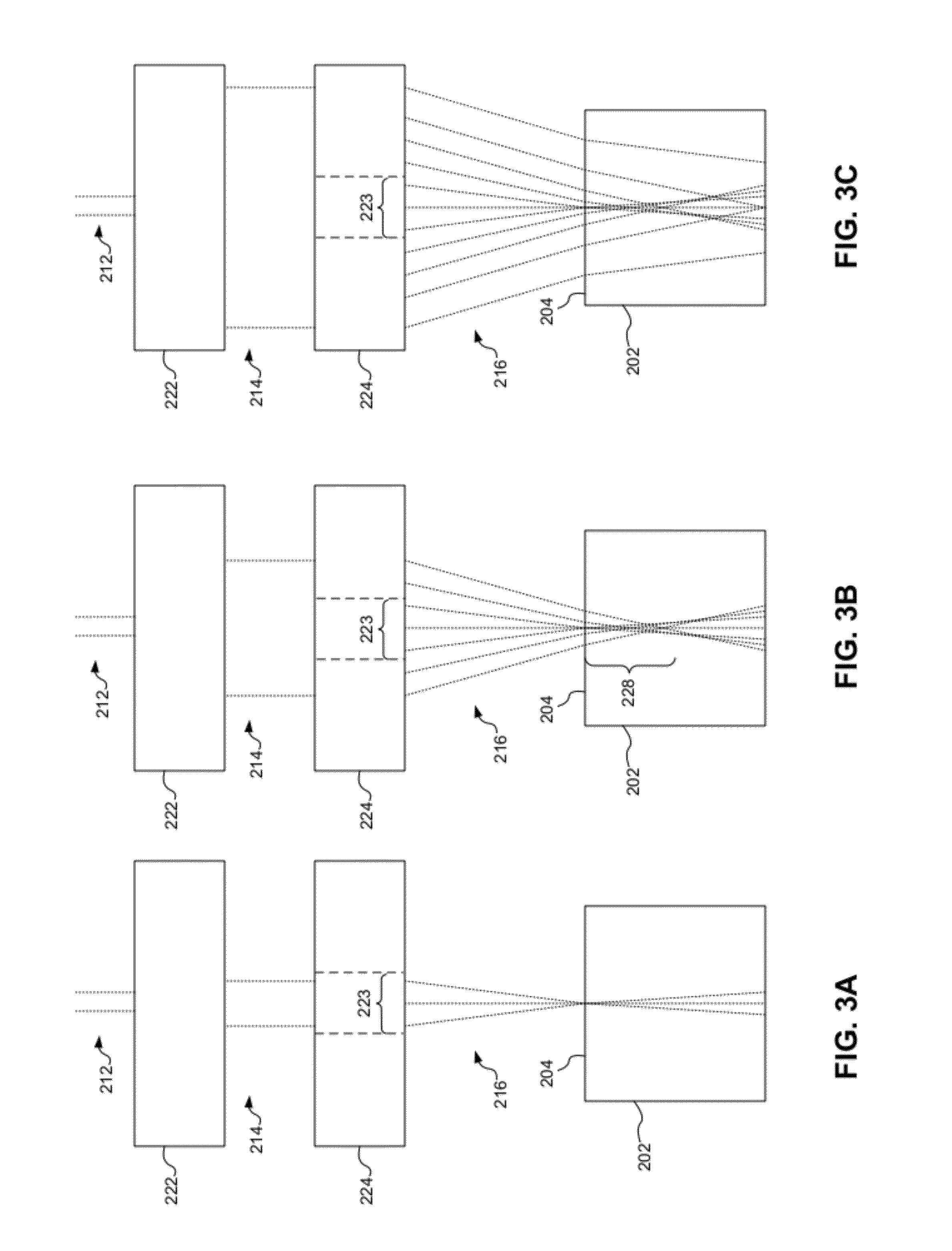
[0023]Systems and methods for laser scribing, consistent with embodiments of the present disclosure, provide extended depth affectation into a substrate or workpiece by focusing a laser beam such that the beam passes into the workpiece using a waveguide, self-focusing effect to cause internal crystal damage along a channel extending into the workpiece. Different optical effects may be used to facilitate the waveguide, self-focusing effect, such as multi-photon absorption in the material of the workpiece, transparency of the material of the workpiece, and optical aberrations of the focused laser beam. The laser beam may have a wavelength, pulse duration, and pulse energy, for example, to provide transmission at least partially through the material and multi-photon absorption in the material. An aberrated, focused laser beam may also be used to provide a longitudinal spherical aberration range sufficient to extend the effective depth of field (DOF) into the workpiece.

[0024]Laser scrib...


PUM

PropertyMeasurementUnit
focal lengthaaaaaaaaaa
kerf widthaaaaaaaaaa
focal depthaaaaaaaaaa

Abstract

Systems and methods for laser scribing provide extended depth affectation into a substrate or workpiece by focusing a laser beam such that the beam passes into the workpiece using a waveguide, self-focusing effect to cause internal crystal damage along a channel extending into the workpiece. Different optical effects may be used to facilitate the waveguide, self-focusing effect, such as multi-photon absorption in the material of the workpiece, transparency of the material of the workpiece, and aberrations of the focused laser. The laser beam may have a wavelength, pulse duration, and pulse energy, for example, to provide transmission through the material and multi-photon absorption in the material. An aberrated, focused laser beam may also be used to provide a longitudinal spherical aberration range sufficient to extend the effective depth of field (DOF) into the workpiece.

Description

CROSS-REFERENCE TO RELATED APPLICATION[0001]The present application is a continuation-in-part of U.S. patent application Ser. No. 12 / 962,050 filed Dec. 7, 2010, which claims the benefit of U.S. Provisional Patent Application Ser. No. 61 / 267,190 filed Dec. 7, 2009, both of which are incorporated herein by reference.TECHNICAL FIELD[0002]The present invention relates to laser machining, and more particularly, laser scribing with extended depth affectation into a workpiece.BACKGROUND INFORMATION[0003]Lasers are commonly used to cut or scribe a workpiece such as a substrate or semiconductor wafer. In semiconductor manufacturing, for example, a laser is often used in the process of dicing a semiconductor wafer such that individual devices (or dies) manufactured from the semiconductor wafer are separated from each other. The dies on the wafer are separated by streets and the laser may be used to cut the wafer along the streets. A laser may be used to cut all the way through the wafer, or p...

Claims


Application Information

Patent Timeline
Patent Type & Authority Applications(United States)
IPC IPC(8): B23K26/38
CPCB23K26/041B23K26/0608B23K2201/40B23K26/0738B23K26/4075B23K26/0676B23K26/042B23K26/40B23K2101/40B23K2103/50
Inventor SERCEL, JEFFREY P.MENDES, MARCOHANNON, MATHEWVON DADELSZEN, MICHAEL
Owner IPG PHOTONICS CORP
Learn More