Substrate cleaving under controlled stress conditions

a technology of stress conditions and substrates, applied in the direction of final product manufacturing, testing/measurement of semiconductor/solid-state devices, transportation and packaging, etc., can solve the problems of insufficient optimum properties of solar cells, many limitations of solar cells, and difficult manufacturing of materials

Inactive Publication Date: 2012-09-20
SILICON GENERAL CORPORATION
View PDF3 Cites 60 Cited by
  • Summary
  • Abstract
  • Description
  • Claims
  • Application Information

AI Technical Summary

Benefits of technology

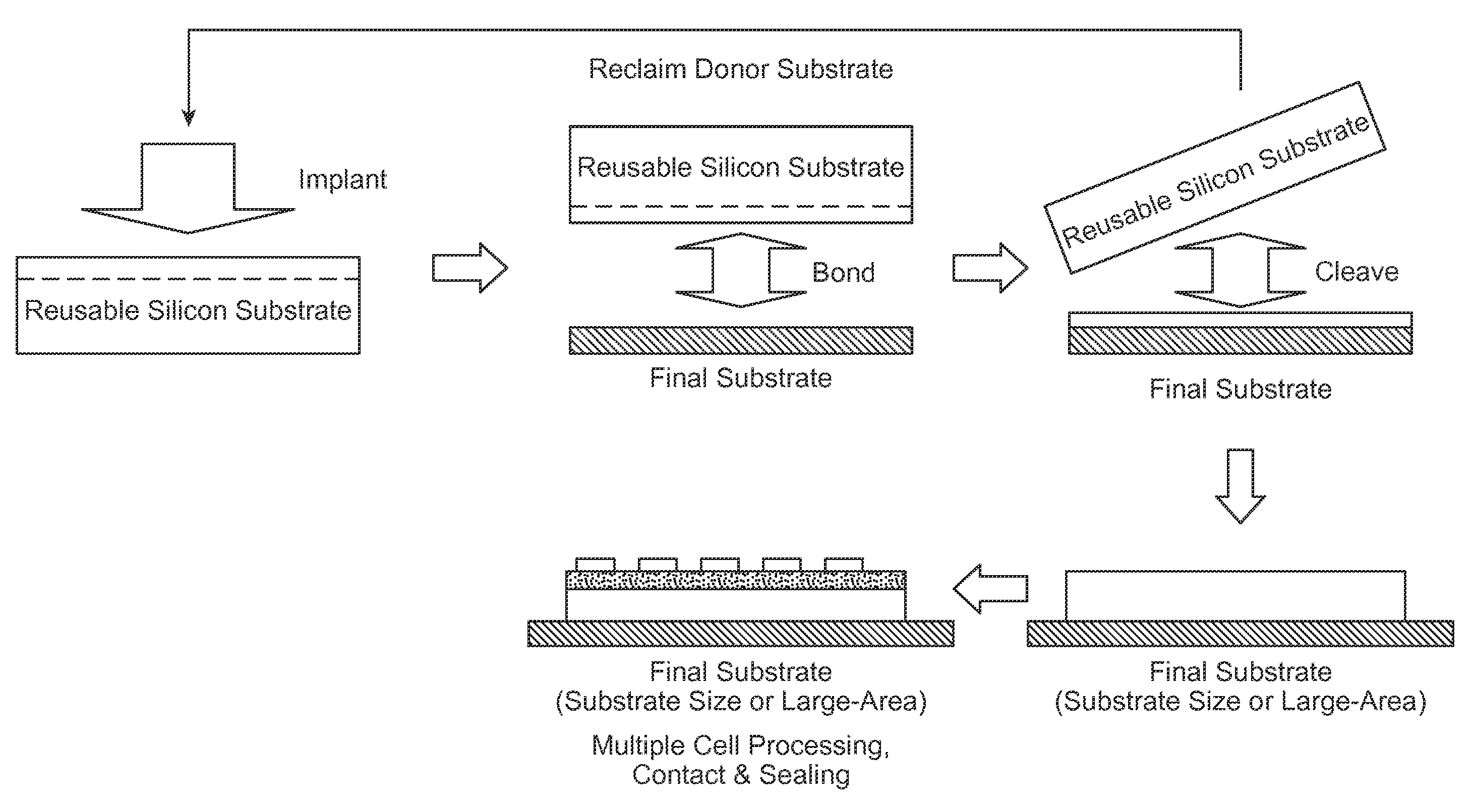
[0007]A thickness of material may be detached from a substrate along a cleave plane, utilizing a cleaving process controlled by a releasable constraint plate. In some embodiments this constraint plate may comprise a plate that can couple side forces (the “P-plate”) and a thin, softer compliant layer (the “S-layer”) situated between the P-plate and the substrate. In certain embodiments a porous surface within the releasable constraint plate and in contact to the substrate, allows the constraint plate to be secured to the substrate via a first pressure differential. Application of a combination of a second pressure differential within a pre-existing cleaved portion, and a linear force to a side of the releasable constraint plate bound to the substrate, generates loading that results in controlled cleaving along the cleave plane. In some embodiments, the linear force is generated by a piezoelectric, motorized linear actuator or pneumatic element that is in physical contact with a side of the constraint plate through an armature. The magnitude and characteristic of the resulting loading can be determined by factors such as stiffness and thickness of the plate and the compliant layer. In certain embodiments, the choice of material property and / or plate dimension can allow use of a single material to act as the P-plate and S-layer combined.

Problems solved by technology

Unfortunately, such petroleum sources have become depleted and have led to other problems.
Although effective, these solar cells still have many limitations.
These materials are often difficult to manufacture.
Although these plates may be formed effectively, they do not possess optimum properties for highly effective solar cells.
Such single crystal silicon is, however, expensive and is also difficult to use for solar applications in an efficient and cost effective manner.
Generally, thin-film solar cells are less expensive by using less silicon material but their amorphous or polycrystal structure is less efficient than the more expensive bulk silicon cells made from single-crystal silicon substrates.

Method used


Image

  • Substrate cleaving under controlled stress conditions
  • Substrate cleaving under controlled stress conditions
  • Substrate cleaving under controlled stress conditions

Examples


example

[0262]These following table shows values of different characteristics of an embodiment which may be utilized to cleave thin layers of monocrystalline silicon from a workpiece.

CHARACTERISTICVALUEWorkpieceWorkpiece materialMono-Si (111)Workpiece thickness (H)5 to 100 mmWorkpiece Young's Modulus187 GPaSurface Energy2.4 J / m2Cleave PlaneCleaved layer thickness (h)20 to 150 μmCleaved portion length (l)60 to 156 mmImplanted ionHydrogenImplant Energy1 to 4 (MeV)Initiation region dose6-9e16 (atoms / cm2)Propagation region dose1 to 6e16 (atoms / cm2)Cleave MomentCompliant layer materialPorous HDPECompliant layer Young's Modulus150 MPaCompliant layer thickness6.3 mmPre-load pressure0 to compressed gas pressurevalue (0 in example)Compressed Gas Pressure0-150 PSI (40 PSI in example)+M10.08 N-m / m (40 PSI and 0 PSIPre-load)Linear P-PlatePlate materialDelrin Acetal Resin PlasticPlate Young's Modulus2.2 GPaPlate width300 mmActuator (Piston) Force10,000 N / m on P-plate(3000 N in example)+P14,280 N / m in ex...


PUM


Abstract

A thickness of material may be detached from a substrate along a cleave plane, utilizing a cleaving process controlled by a releasable constraint plate. In some embodiments this constraint plate may comprise a plate that can couple side forces (the “P-plate”) and a thin, softer compliant layer (the “S-layer”) situated between the P-plate and the substrate. In certain embodiments a porous surface within the releasable constraint plate and in contact to the substrate, allows the constraint plate to be secured to the substrate via a first pressure differential. Application of a combination of a second pressure differential within a pre-existing cleaved portion, and a linear force to a side of the releasable constraint plate bound to the substrate, generates loading that results in controlled cleaving along the cleave plane.

Description

CROSS-REFERENCES TO RELATED APPLICATIONS[0001]The instant nonprovisional patent application is a continuation-in-part of U.S. Nonprovisional patent application Ser. No. 12 / 730,113 filed Mar. 23, 2010, which is a continuation of U.S. Nonprovisional patent application Ser. No. 11 / 852,088 filed Sep. 7, 2007, which claims priority to U.S. Provisional Patent Application No. 60 / 825,095 filed Sep. 8, 2006. The instant nonprovisional patent application is also a continuation-in-part of U.S. Nonprovisional patent application Ser. No. 12 / 435,230 filed May 4, 2009, which claims priority to U.S. Provisional Patent Application No. 61 / 051,307 filed May 7, 2008. The instant nonprovisional patent application is also a continuation-in-part of U.S. Nonprovisional patent application Ser. No. 12 / 460,898 filed Jul. 24, 2009, which claims priority to U.S. Provisional Patent Application No. 61 / 092,683 filed Aug. 28, 2008. Each of these patent applications is incorporated by reference in its entirety herei...

Claims


Application Information

Patent Timeline
Patent Type & Authority Applications(United States)
IPC IPC(8): H01L21/304
CPCH01L21/67092H01L21/76254H01L21/7813H01L31/03921H01L31/068H01L21/683H01L31/1804H01L31/1892Y02E10/544Y02E10/547H01L21/304H01L31/0687Y10T225/30Y10T225/10Y10T225/393B26F3/002Y02P70/50H01L31/18H01L21/6835H01L22/12
Inventor HENLEY, FRANCOISLAMM, ALCHOW, YI-LEI
Owner SILICON GENERAL CORPORATION
Why Eureka
Try Eureka