Conducting a Transaction with an Electronic Card

a technology of electronic cards and transactions, applied in the field of conducting transactions with electronic cards, can solve problems such as financial dollar losses, counterfeiting of magnetic stripe plastic cards, and growing fraud around the world

Active Publication Date: 2012-09-20
DFS SERVICES
View PDF8 Cites 29 Cited by
  • Summary
  • Abstract
  • Description
  • Claims
  • Application Information

AI Technical Summary

Benefits of technology

[0014]Accordingly, it is a primary object of the present invention to provide for improved use of an electronic card to complete a transaction through use of transaction specific data dynamically generated.

Problems solved by technology

However, the relative ease of reading and encoding or re-encoding of the magnetic stripe data has made the magnetic stripe plastic card subject to counterfeiting, copying the data to one or more cards (skimming) and other fraud abuses.
Skimming fraud is growing around the world and has reached financial dollar losses that call for immediate solutions.
The Smart Cards did reduce some types of fraud but the cards where much more expensive than a magnetic stripe card and the magnetic stripe readers at the point-of-transaction had to be replaced with readers that could read the data storage chip and the magnetic stripe by either contact or RF contact-less data transmission.
These cost factors and the large changes in the existing infrastructure built up around the magnetic stripe plastic card systems and applications have prevented the rapid and more general acceptance of Smart Cards at point-of-transaction.
Another factor in the slow acceptance of Smart Cards has been the lack of visible benefits to the end user or consumer.
Internationally, the need is even more dire, with fraud tending from 25 to 40 basis points and 60 percent of that due to skimming.
Nevertheless, merchants in the United States and elsewhere are reluctant to invest the resources necessary to change all of their current magnetic-card transaction equipment for various reasons, including cost, convenience, disruption to business and reliability.

Method used


Image

  • Conducting a Transaction with an Electronic Card
  • Conducting a Transaction with an Electronic Card
  • Conducting a Transaction with an Electronic Card

Examples


first embodiment

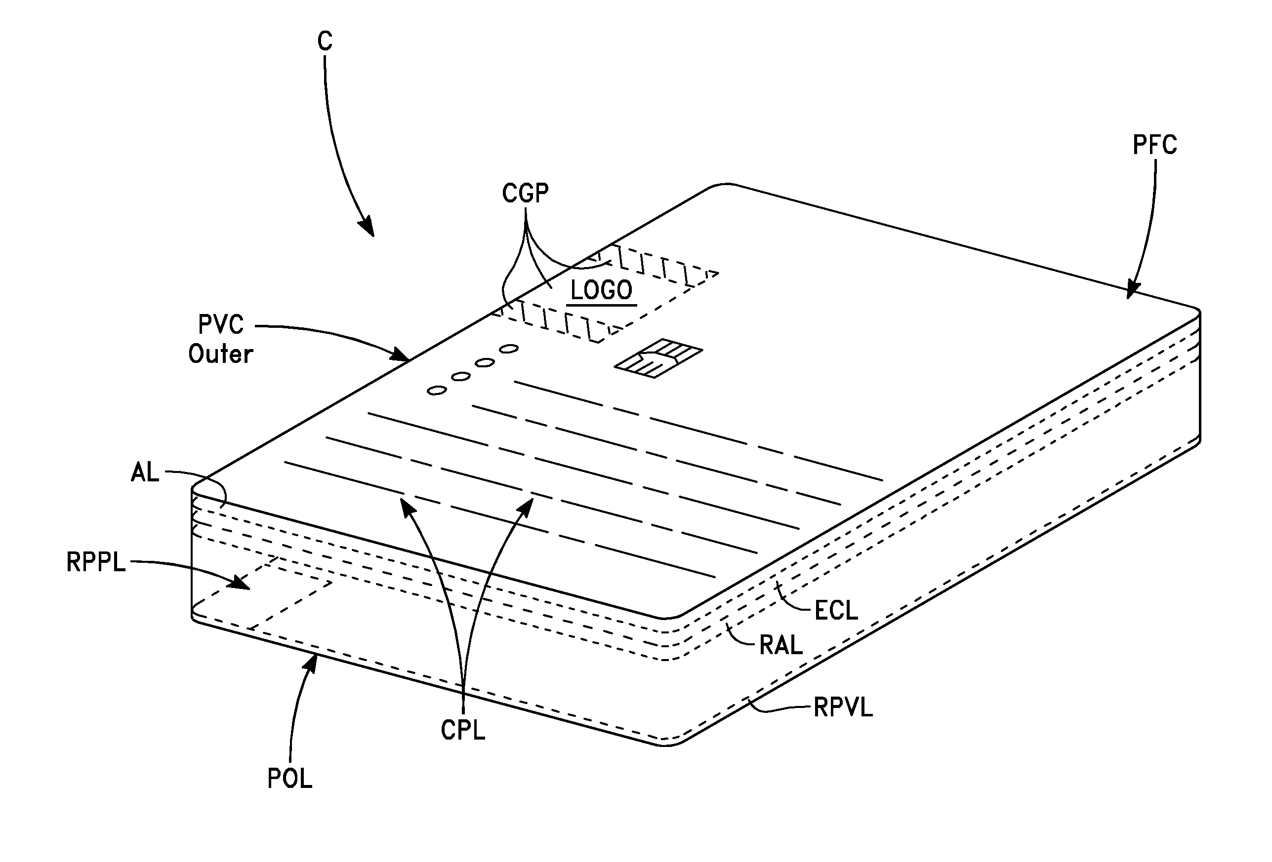
[0107]Referring to FIG. 3, a functional “layer” diagram of the inventive transaction card 1 is shown. The layers are simplified for illustrative purposes in FIG. 3 and are not nearly shown to the scale and geometry that would be present in a commercial embodiment. A main PCB assembly 237 that comprises the components of the inventive transaction card 1 includes component layers: a finished stack assembly 254, a die carrier subassembly 256, a cover layer 233, and broadcaster core 178 disposed in the body of the assembly 1. The finished stack assembly 254 is also comprised of two sub-layers the PCB layout layer 218 and the stiffener layer 226.

[0108]FIG. 4 is a detailed view of the components of the main assembly body 237 of the transaction card in a first embodiment 1.

[0109]The following table may be used with reference to FIG. 4 and FIGS. 7-231 to identify various features, components and configurations for the first illustrative embodiment of the invention.

TABLE 1.1Key #1 FIGS. 4 an...

second embodiment

[0112]FIG. 6 is a detailed view of the main assembly 253 of the transaction card 10. The following table may be used with reference to FIG. 6 and FIGS. 24-39 to identify various features, components and configurations for the second illustrative embodiment of the invention.

TABLE 2.1KEY TO FIGS. 6; 24-39BFIGS.IndexDescription of Component(if relevant)BT13 V BATTERYFIG. 39N / AFINISHED STACK UP ASSEMBLYFIG. 24N / ACOVER FR4 PLATED WITRIPSWITCHFIG. 6C2CAP, CER, 22 pF, 0201, ±10% COG,FIG. 3925 V, X5RC8CAP, CER, 1000 Pf, 0201, ±10% COG,FIG. 3925 V, X7RC3-C7,CAP, CER, .1 NF, 0201, ±10%FIG. 39C10-C19,6.3 V, X5RC21-C25C9CAP, CER, .022 pF,FIG. 390201 + 80 / −20%.6.3 V, Y5VC20, C1CAP, CER, .033 pF, 0201, +80 / −20%, Y5VFIG. 39LED1-LED3LED YELLOW 0603, 2.4 V,FIG. 3935 mcd, 589 nmLED4LED GREEN 0603, 2.6 V, 3.7 mcdFIG. 39LED5LED RED 0603, 2.5 V, 4.2 CANDELAFIG. 39Q2, Q3CP324-2N7002-WS DIE,FIGS. 38, 39N CHANNEL MOSFETR25RES, CER, 00, 0402FIG. 39R1, R22RES, CER, 4.7K0, 0402, 1 / 16 W, ±5%FIG. 39R2RES, CER, ...

embodiment 51

[0149]A printed circuit board (PCB) layer in an alternate embodiment 51 is shown in FIGS. 50A and B, from front and side views, respectively 51-PCB. The alternate embodiment implements features and configuration, as well as omits others, that are included in the first 1 and second 10 embodiments discussed above, in FIGS. 3-4; 6-23 and 5-6 and 7-40, respectively. FIG. 50B illustrates the positioning of the mask and top and bottom layer(s) in the circuit board for the alternate card 51pcb.

[0150]FIG. 51 illustrates the layer 1 mask-51-L1-M. FIG. 52 shows the top layer 51-L1 for the alternate PCB and FIG. 53 shows the layer 2 bottom, 51-L2.

[0151]The magnetic field illustrated by the magnetic lines of flux generated by the broadcaster coil and is extended outward from the coil in continuous paths always passing thru the magnetic stripe broadcaster coil and then out into the space around the coil, re-entering the coil to complete the continuous path of flux lines. The flux lines have the...


PUM


Abstract

An apparatus and process for conducting a transaction with an electronic card that dynamically generates transaction specific data determines whether the transaction is being conducted with a smart card reader or with a magnetic stripe reader. A smart card reader mode is activated if the transaction is being conducted with a smart card reader; a magnetic stripe reader mode is activated if the transaction is being conducted with a magnetic stripe reader. The electronic card is activated from a reduced power mode to a full power mode after either the smart card reader mode or the magnetic stripe reader mode is activated and the dynamic field of data is not generated until the full power mode is activated.

Description

CROSS-REFERENCE TO RELATED APPLICATIONS[0001]The present application is a continuation application of U.S. patent application Ser. No. 13 / 102,991, filed May 6, 2011, which is a continuation of U.S. Ser. No. 12 / 726,868, now issued as U.S. Pat. No. 7,954,724, which was a continuation application of U.S. Ser. No. 11 / 413,595, filed Apr. 27, 2006, which claimed the priority benefit of U.S. Ser. No. 60 / 675,388, filed Apr. 27, 2005, all of which are specifically incorporated herein by reference. This application is also a continuation-in part application of U.S. Ser. No. 11 / 391,719, filed Mar. 27, 2006, which claimed the priority benefit of U.S. Ser. No. 60 / 594,300 filed Mar. 26, 2005, all of which are specifically incorporated herein by reference. This application sets forth the disclosure of U.S. Ser. No. 60 / 675,388.BACKGROUND[0002]A magnetic stripe plastic card contains a magnetic tape material much like the magnetic tape used in digital data recording. The magnetic stripe consists of a...

Claims


Application Information

Patent Timeline
Patent Type & Authority Applications(United States)
IPC IPC(8): G06K19/073G06F7/04
CPCG06K19/0702G06K19/07722G06K19/077G06K19/06G06K19/07B42D25/21
Inventor POIDOMANI, MARKZIEGLER, JOANFOO, ERICALON, ZIVMCGUIRE, CHARLESROUTHENSTEIN, LAWRENCE
Owner DFS SERVICES
Why Eureka
Try Eureka