Aircraft engine attachment pylon

a technology for aircraft engines and pylons, which is applied in the direction of aircraft power plants, power plant construction, power plant types, etc., can solve the problems of increasing cost and time, generating non-negligent aerodynamic disturbances, and limited access inside the pylons, so as to reduce the lateral dimension of the assembly, easy to access, and easy to access

Inactive Publication Date: 2012-09-20
AIRBUS OPERATIONS (SAS)
View PDF2 Cites 9 Cited by
  • Summary
  • Abstract
  • Description
  • Claims
  • Application Information

AI Technical Summary

Benefits of technology

[0016]The main advantage of this solution is that it reduces the lateral dimension of the assembly formed by the box and the lateral fittings, due to the specific inclination of the attachment interfaces at 45°, which is significantly different from the solution according to prior art according to which these interfaces were horizontal.
[0017]Furthermore, since the bolts preferably have the same 45° inclination from the vertical, they are easier to access. This means that the ends of the bolts can be moved further from the lateral panels, so that they can be accessed more easily when tightening.
[0018]Furthermore, since the lateral dimension is significantly reduced, there is no longer any need to adopt the previously selected mounting system in which lateral fittings were inserted between the lower spar and the lateral panels. The lateral fittings can be fixed on the outside on lateral panels, without generating significant aerodynamic disturbances on the secondary flow. In this preferred case, the assembly then no longer requires recesses in the lateral panels for the passage of lateral fittings, nor a choke at the lower spar, nor any particular complex shape of the inner transverse rib located adjacent to these lateral fittings, which enabled the “sandwich” mounting of the fittings. The result is a simplified design, considerably limiting shape discontinuities on the above-mentioned elements which results in significant cost and mass savings.
[0019]Finally, due the inclination of the two attachment interfaces at 45° from the vertical, each half-attachment is capable of not only resisting forces along the vertical direction, but also forces along the transverse direction. The shear pin system used in prior art for resisting transverse forces is therefore no longer required. This results in a saving in mass and simplification of the design of the attachment pylon.

Problems solved by technology

However, access inside the pylon is often very limited, which inevitably leads to mounting difficulties that tend to increase cost and time.
Furthermore, despite the interposition of these fittings between the lower spar and the lateral panels, the lateral dimension remains large and therefore generates non-negligible aerodynamic disturbances of the secondary flow.
These shape discontinuities on the above-mentioned elements generate mechanical weaknesses that have to be compensated, usually increasing cost and mass.
These means are additional to the lateral fittings that resist vertical forces through the bolts passing through them, significantly increasing the complexity of this zone of the attachment pylon.

Method used


Image

  • Aircraft engine attachment pylon
  • Aircraft engine attachment pylon
  • Aircraft engine attachment pylon

Examples


Embodiment Construction

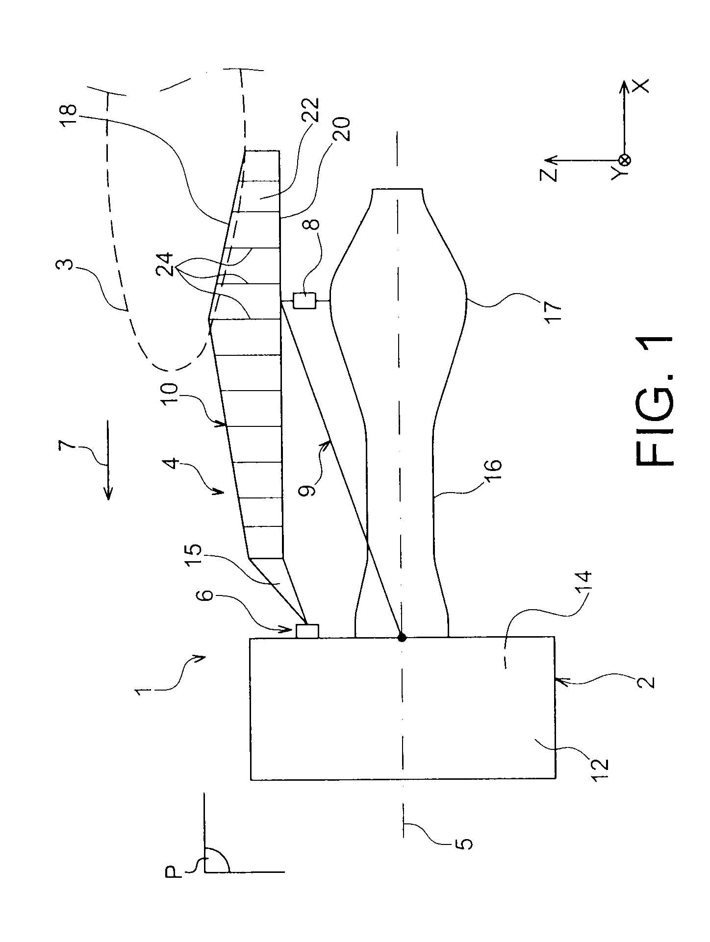
[0040]FIG. 1 shows an engine assembly 1 for an aircraft that will be fixed under a wing 3 of this aircraft (not shown), this assembly 1 comprising an attachment pylon 4 according to a preferred embodiment of this invention.

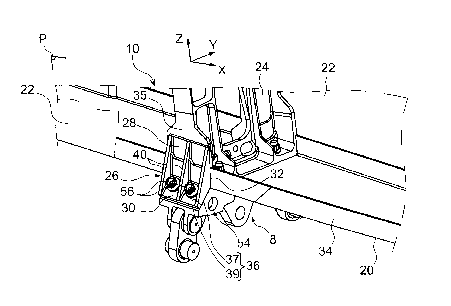
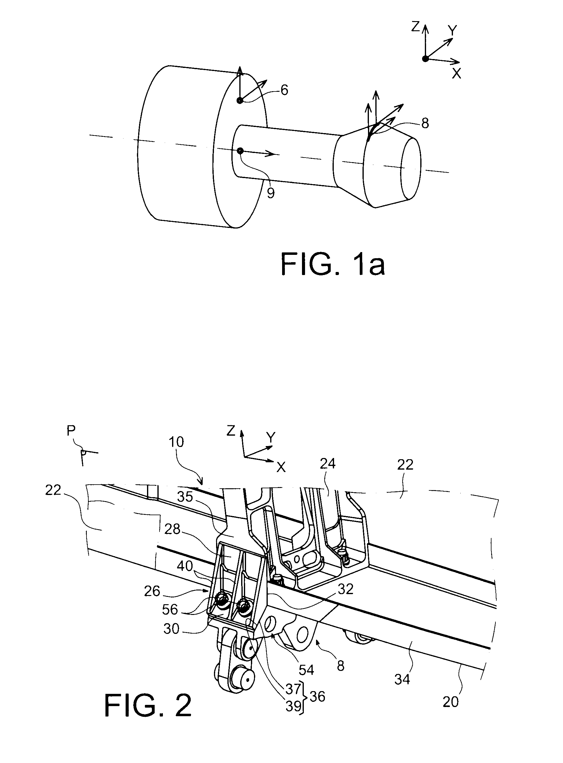
[0041]Globally, the engine assembly 1 is composed of an engine such as a turbojet 2 and the attachment pylon 4, this pylon in particular being provided with a plurality of engine attachments 6, 8, 9 and a rigid structure 10 called the primary structure supporting these attachments. For information, it should be noted that the assembly 1 is designed to be surrounded by a pod (not shown) and that the attachment pylon 4 is provided with another series of attachments (not shown) used to suspend this assembly 1 under the aircraft wing.

[0042]Throughout the following description, by convention, X refers to the longitudinal direction of the pylon 4 that is also considered to be the same as the longitudinal direction of the turbojet 2, this X direction being parallel to a ...


PUM


Abstract

The invention relates to an aircraft engine attachment pylon, comprising a box formed by the assembly of a first spar (18), a second spar (20) and two lateral panels (22), the pylon also comprising an aft engine attachment (8) fitted with an aft attachment body (54), and also provided with two lateral fittings (26) associated with the two lateral panels (22) to which they are fixed and from which they project laterally outside the caisson, each fitting (26) forming a plane attachment interface (36) with the attachment body (54) through which bolts pass (56).
According to the invention, each interface (36) is in the shape of a straight segment inclined at 45° from the vertical direction (Z) as seen in section on any transverse plane of the pylon passing through it.

Description

TECHNICAL FIELD[0001]This invention relates in general to an attachment pylon for an aircraft engine such as a turbojet. This type of attachment pylon is also called an EMS (Engine Mounting Structure), and can be used to suspend the turbojet below the aircraft wing, or to mount this turbojet above this wing through a plurality of engine attachments.STATE OF THE PRIOR ART[0002]Such an attachment pylon is designed to form the attachment interface between an engine such as a turbojet and an aircraft wing. It transmits forces generated by a turbojet associated with an aircraft to the structure of this aircraft, and it also enables routing of fuel, electrical, hydraulic and air systems between the engine and the aircraft.[0003]The pylon comprises a rigid structure, also called the primary structure, frequently of the “box” type, in other words formed from the assembly of upper and lower spars and two lateral panels connected to each other through transverse inner ribs, to transmit forces...

Claims


Application Information

Patent Timeline
Patent Type & Authority Applications(United States)
IPC IPC(8): B64D27/12
CPCB64D2027/264B64D27/26
Inventor MARCHE, HERVE
Owner AIRBUS OPERATIONS (SAS)
Why Eureka
Try Eureka