

Gas cell unit, atomic oscillator and electronic apparatus
a technology of atomic oscillator and gas cell, which is applied in the field of gas cell unit, atomic oscillator, electronic apparatus, can solve problems such as deviation of output frequency, and achieve the effect of excellent reliability
- Summary
- Abstract
- Description
- Claims
- Application Information
AI Technical Summary
Benefits of technology
Problems solved by technology
Method used
Image

Examples
first embodiment
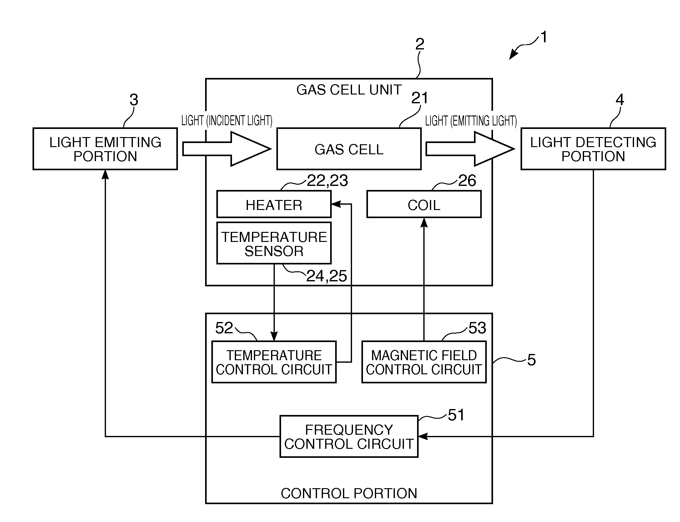
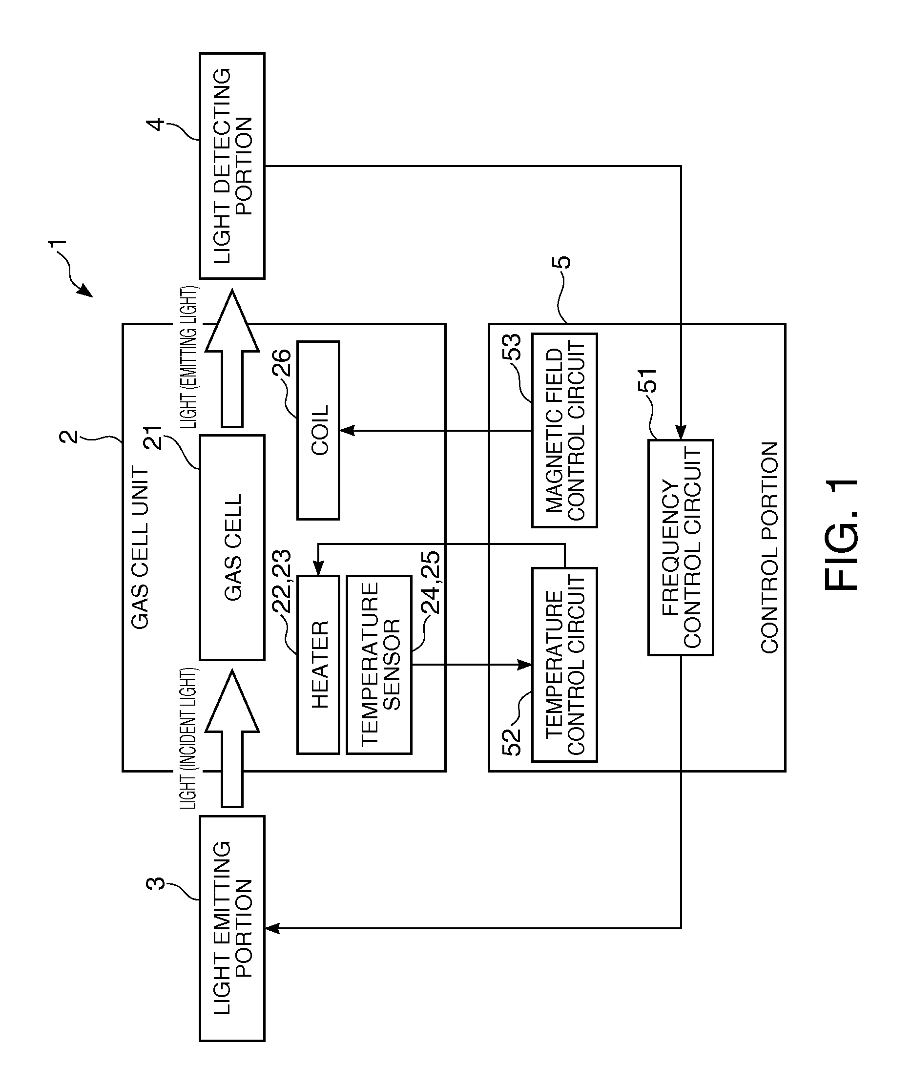
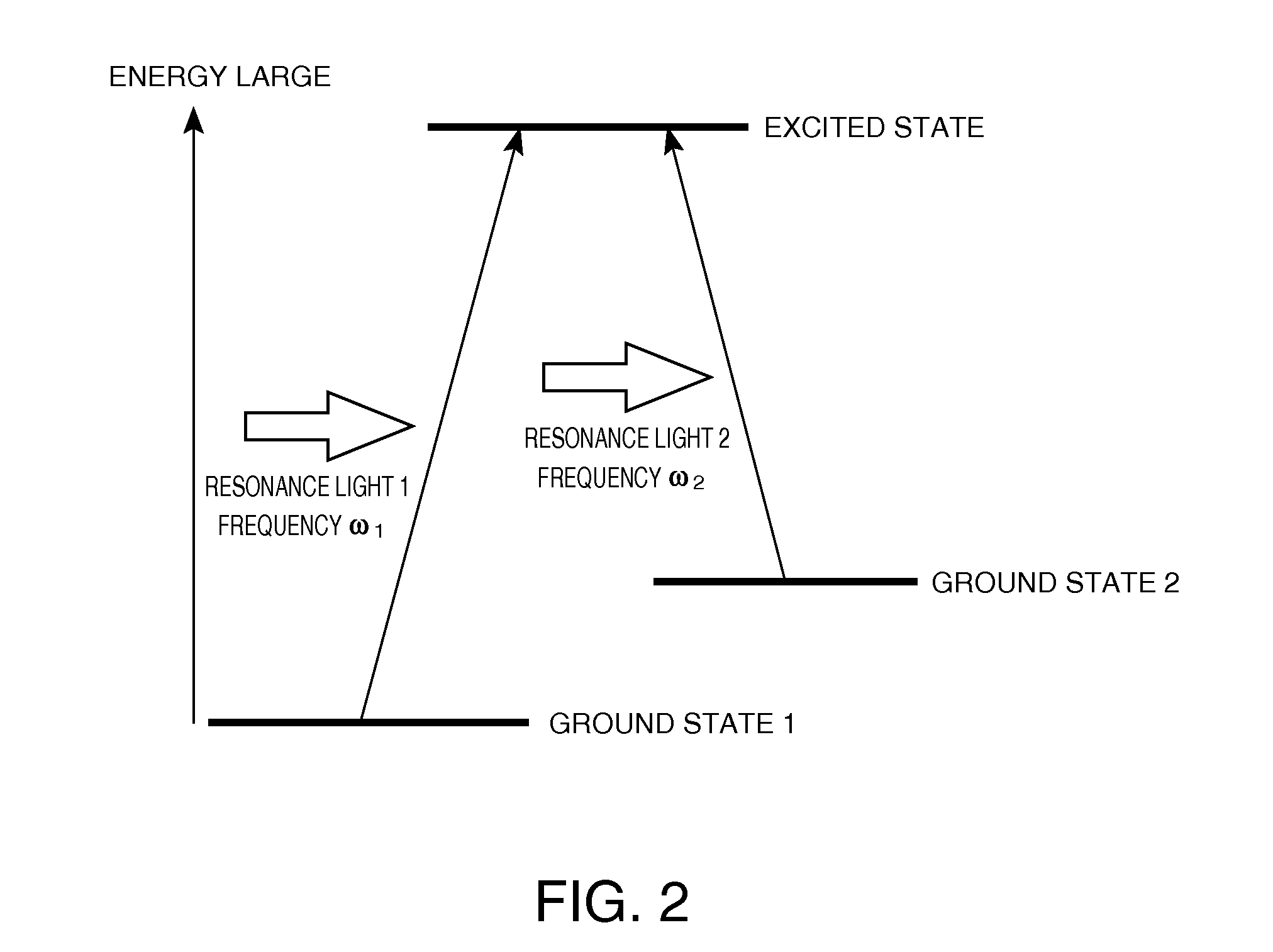
[0046]FIG. 1 is a block diagram that shows a schematic configuration of an atomic oscillator according to a first embodiment of the invention. FIG. 2 is a diagram for describing the energy state of an alkali metal in a gas cell included in the atomic oscillator shown in FIG. 1. FIG. 3 is a graph that shows a relationship between a frequency difference of two lights from a light emitting portion and a detection intensity of a light detecting portion in the light emitting portion and the light detecting portion included in the atomic oscillator shown in FIG. 1. FIG. 4 is a perspective view that shows a schematic configuration of a gas cell unit included in the atomic oscillator shown in FIG. 1. FIG. 5 is a cross-sectional view that shows the gas cell unit shown in FIG. 4. FIG. 6 is a diagram that shows a heating resistor included in the heater shown in FIG. 5. FIG. 7 is a diagram for describing the magnetic field generated due to the electric conduction to the heating resistor include...
second embodiment
[0128]Next, a second embodiment of the invention will be described.
[0129]FIG. 8 is a diagram that shows a heater included in a gas cell unit according to the second embodiment of the invention.
[0130]The gas cell unit according to the present embodiment is the same as that of the gas cell unit according to the first embodiment mentioned above except that the configuration (mainly a shape) of a heating resistor of the heater differs.
[0131]In addition, in the description mentioned below, differences between the gas cell unit of the second embodiment and that of the first embodiment will be mainly described, and similar matters are omitted. Furthermore, in FIG. 8, the same configurations as those of the embodiments mentioned above are denoted by the same reference numerals.
[0132]The gas cell unit 2A shown in FIG. 8 is configured so that, in the gas cell unit 2 of the first embodiment, a heater 22A is provided instead of the heater 22. In addition, although not shown, the gas cell unit 2...
third embodiment
[0138]Next, a third embodiment of the invention will be described.
[0139]FIG. 9 is a diagram showing a heater included in a gas cell unit according to the third embodiment of the invention.
[0140]The gas cell unit according to the present embodiment is the same as that of the gas cell unit according to the first embodiment mentioned above except that the configuration (mainly a shape) of a heating resistor of the heater differs.
[0141]In addition, in the description mentioned below, the differences between the gas cell unit of the third embodiment and that of the first embodiment will be mainly described, and similar matters are omitted. Furthermore, in FIG. 9, the same configurations as those of the embodiments mentioned above are denoted by the same reference numerals.
[0142]The gas cell unit 2B shown in FIG. 9 is configured so that the gas cell unit 2 of the first embodiment is provided with a heater 22B instead of the heater 22. In addition, although not shown, the gas cell unit 2B ...
PUM
 Abstract
Description
Claims
Application Information