[0012]A large part of the C-arm structure therefore becomes a kind of control, i.e. the limitation that the C-arm can only be controlled from one location, in some cases only by one person, no longer exists. By installing a small number of sensors, the implementation costs and complexity can be reduced compared to a solution achieving a comparable effect. Lastly, the operator control concept is intuitive, so that expensive training of the operating personnel, such as the training that would be required using e.g. pushbuttons or joysticks, is no longer necessary.
[0017]In other words, the C-arm is moved by the actuator, e.g. a motor, in a direction in which the operator attempts to push the C-arm. As the direction of motion of the actuator is usually predefined by an axis, or rather a translatory travel possibility, it may be sufficient if the direction of motion coincides with a
force direction component. As a result, the operator will have the impression that his / her applied force would move the C-arm essentially in the direction of the force. This constitutes a very intuitive method for motor-assisted C-arm travel. At the same time, the method improves safety, as the change in position is aligned such that the C-arm evades the force and the movement comes to a halt if the operator ceases to apply force to the C-arm. Safety is further improved in that, in the event of a collision or if the C-arm comes up against an obstacle, the C-arm deforms counter to the direction of travel and therefore also counter to the direction of the force applied by the operator, thereby slowing down or stopping the movement of the C-arm.
[0021]This feature makes the travel even more intuitive, as it provides an easily comprehensible relationship between size of force and travel velocity.
[0023]Depending on the geometric ratios of the C-arm, when a force is applied externally, the deformation will be of varying size at different points of the C-arm, i.e. the sensor will measure different deformation sizes depending on its position on the C-arm. In order to obtain a large sensor output
signal, it is advisable to determine the C-
arm position which exhibits a large or rather the maximum deformation in the event of a particular application of force. This position can be determined by a series of measurements in which the sensor signal is measured at a plurality of positions. Another possibility is to determine, by
structural analysis of the C-arm, positions which exhibit a greater deformation than other positions when a directional force is applied. Such a
structural analysis can be performed by mathematical calculation or by computer-assisted analysis, e.g. based on a
finite element method (FEM). In the
structural analysis, which can result in a mechanical structural model of the C-arm, geometric aspects and material properties of the C-arm must particularly take into account. Sensor placement relates to both the position of the sensor and its orientation, as both parameters affect the sensor signal for a given direction of action. The sensor can be mounted on the C-arm, e.g. by
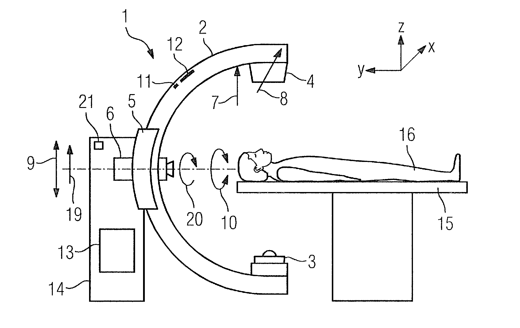
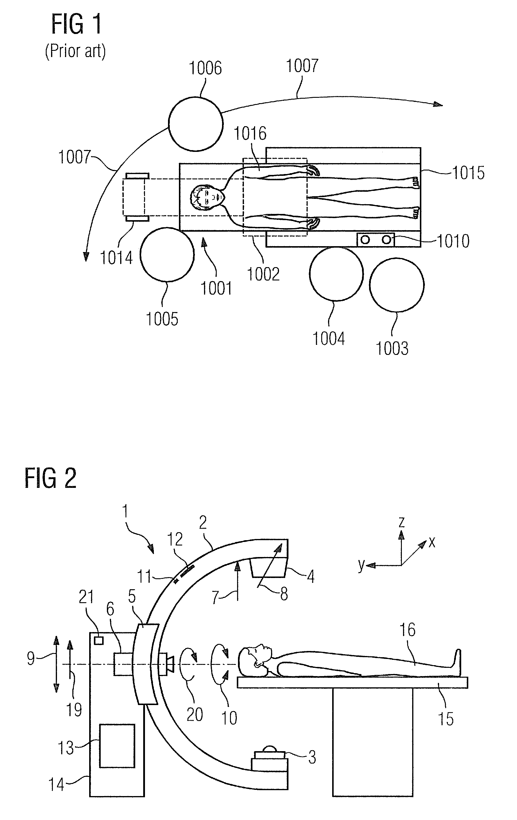
adhesive bonding or other attachment method or attachment means, or it can be incorporated in the material of the C-arm. A criterion for selecting the sensor position can be not only high sensor sensitivity to deformations but also selectivity in respect of the direction of action. For example, it is desirable that deformation of the C-arm in a direction in which the C-arm cannot travel also does not produce an output signal. This becomes increasingly important the more movement axes an X-ray
machine possesses. It is also advisable to place a plurality of single-axis sensors or at least one multi-axis sensor such that the direction of an acting force can be reconstructed. For example, a plurality of single-axis strain gages can be positioned such that they are sensitive in differing degrees to applications of force from different directions, and the direction of force can therefore be reconstructed by linearly combining the individual sensor signals. In addition, general requirements such as good
accessibility, simple attachment possibilities, etc. play a role in sensor positioning.
[0025]The use of two sensors whose output signals are subtracted from one another generally has the
advantage, depending on the positioning of the sensors, that the difference signal is less prone to interference due to e.g.
voltage, temperature,
moisture, sensor material variations or aging effects or that the difference signal has a better level, i.e. signal-to-
noise ratio. When a first sensor and a second sensor, termed a
reference sensor, is used, the
reference sensor can be placed such that a deformation of the C-arm does not significantly affect the output signal of the
reference sensor. However, the output signal of the reference sensor changes in the same way as that of the first sensor in the event of a change in the operating conditions, such as temperature or
humidity or
operating voltage. By taking the difference, the sensor signals caused by variations in the operating conditions are compensated, so that only the sensor signal change due to the deformation of the C-arm undergoes further
processing. Another possibility is to place the sensors such that the deformation of the C-arm in the case of the reference sensor changes inversely to that in the case of the first sensor, e.g. a placement of the sensors such that the deformation of the C-arm causes the first sensor to lengthen and the reference sensor to shorten. The difference between the two sensor signals is again compensated for operating condition fluctuations and has an amplitude twice as large as that of an individual sensor.

