Driving device for vehicle

a technology for driving devices and vehicles, applied in the direction of battery/cell propulsion, engine starters, gearing, etc., can solve the problems of vibration, deficiency of the first rotating electrical machine, and inability to operate normally,

Inactive Publication Date: 2012-09-27
AISIN AW CO LTD
View PDF4 Cites 16 Cited by
  • Summary
  • Abstract
  • Description
  • Claims
  • Application Information

AI Technical Summary

Benefits of technology

[0032]According to this configuration, it is possible to realize the electric traveling mode in which the torque of the second rotating ele

Problems solved by technology

Therefore, in the configuration of JP-A-2010-76678, the torque of the first rotating electrical machine may be deficient depending on the magnitude of the vehicle speed with respect to the torque necessary to increase the rotation speed of the internal combustion engine, such that there is a concern in that the internal combustion engine may not be started up, or vibration may occur at the time of starting up the internal combustion engine.
However, as is clea

Method used


Image

  • Driving device for vehicle
  • Driving device for vehicle
  • Driving device for vehicle

Examples


first embodiment

1. First Embodiment

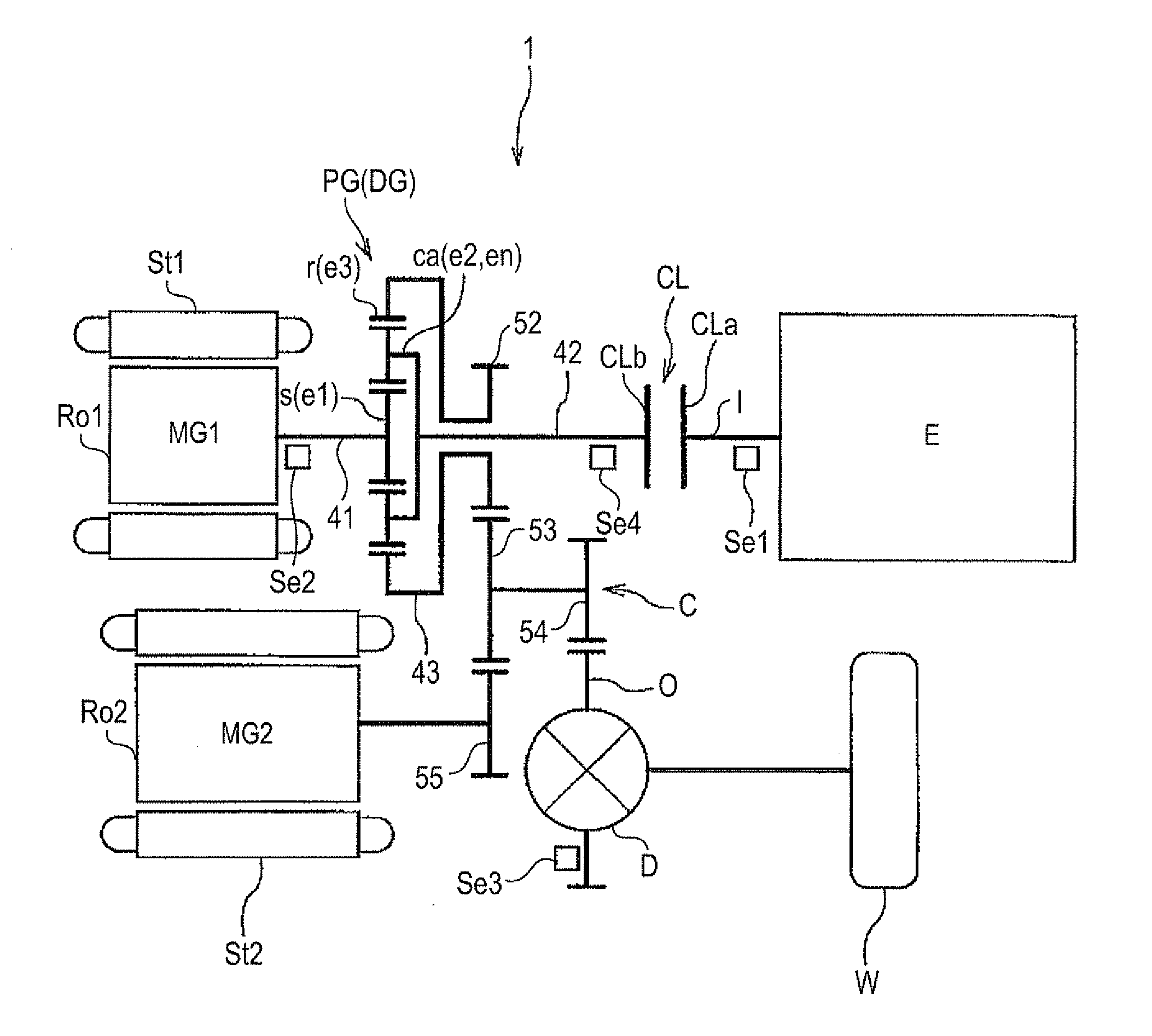
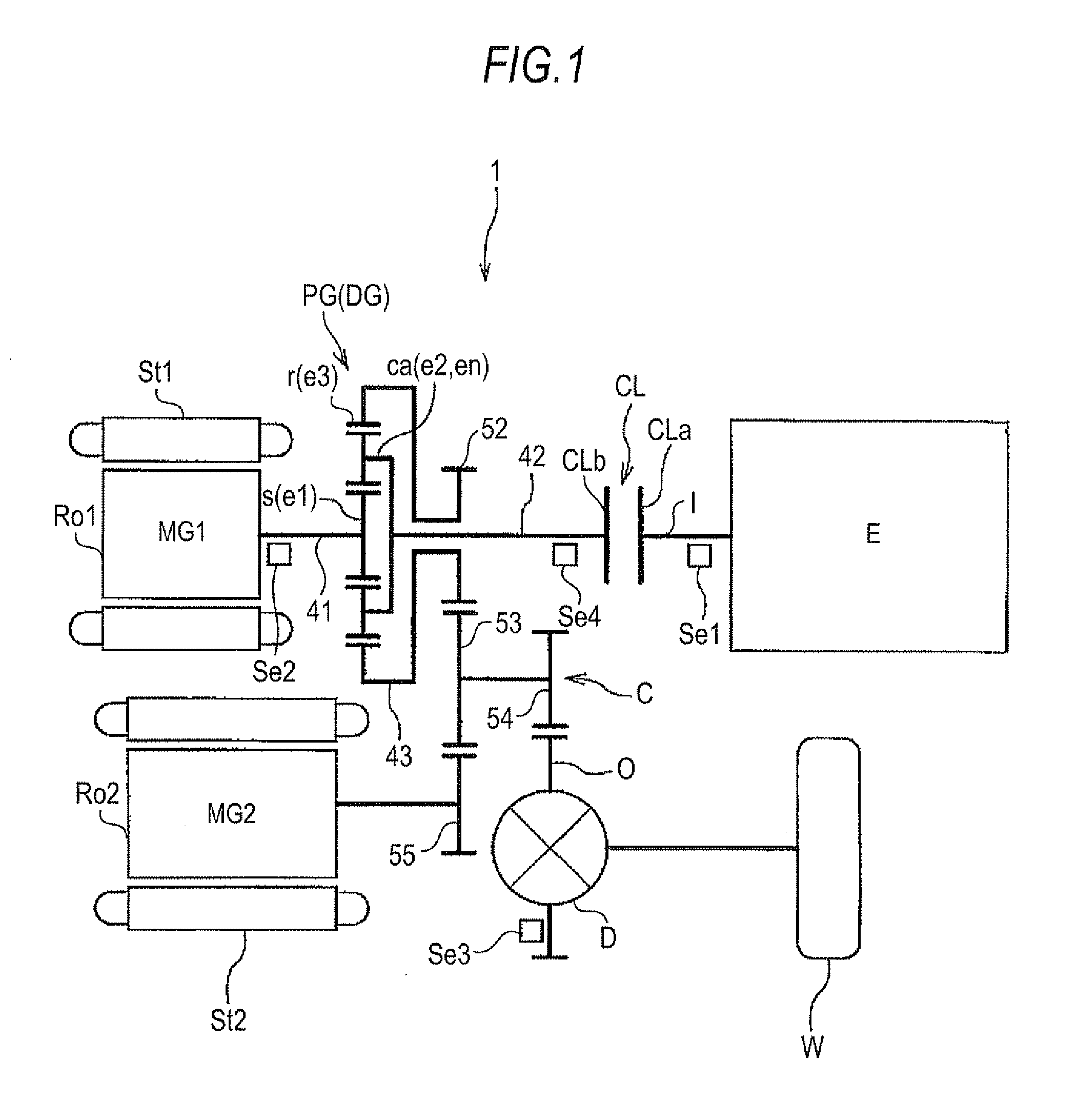
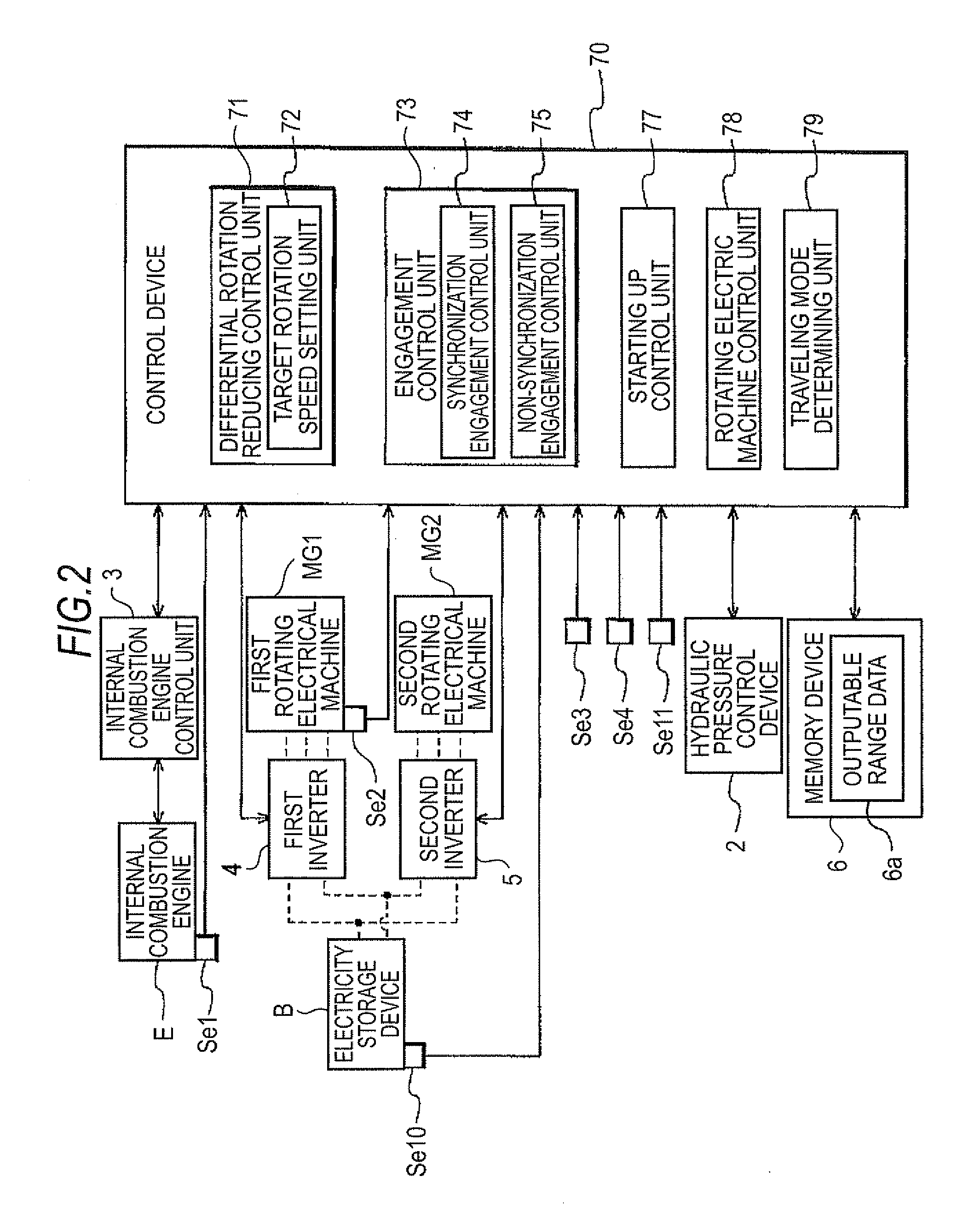
[0056]A first embodiment of a driving device for a vehicle according to the invention will be described with reference to the attached drawings. As shown in FIG. 1, the driving device 1 for a vehicle according to this embodiment is configured by a driving device (driving device for a hybrid car) to drive a vehicle (a hybrid car) including both an internal combustion engine E and rotating electrical machines MG1 and MG2 as a driving power source for wheels. In addition, the driving device 1 for a vehicle according to this embodiment includes a control device 70 (refer to FIG. 2) and this control device 70 controls an operation of each driving power source and a frictional engagement device CL on the basis of a system configuration shown in FIG. 2. In addition, in FIG. 2, broken lines represent transmission paths of electric power, and solid line arrows represent transmission paths of various pieces of information.

[0057]As shown in FIG. 1, in this embodiment, a diff...

second embodiment

2. Second Embodiment

[0163]Next, a second embodiment of the driving device for a vehicle according to the invention will be described with reference to FIGS. 15 and 16. As shown in FIG. 15, the driving device 1 for a vehicle according to this embodiment is configured basically with the same configuration as the first embodiment except for an arrangement position of the frictional engagement device CL. Hereinafter, a configuration of the driving device 1 for a vehicle according to this embodiment will be mainly described based on the differences from the first embodiment. In addition, it is assumed that configurations not specifically described are the same as the first embodiment.

[0164]As shown in FIG. 15, in the driving device 1 for a vehicle according to this embodiment, the frictional engagement device CL is provided at a power transmission path between the output member O and the rotational element (the third rotational element e3) of the differential gear unit DG, not between th...

third embodiment

3. Third Embodiment

[0173]Next, a third embodiment of the driving device for a vehicle according to the invention will be described with reference to FIGS. 17 and 18. As shown in FIG. 17, the driving device I for a vehicle according to this embodiment is configured basically with the same configuration as the first embodiment except for an arrangement position of the frictional engagement device CL. Hereinafter, a configuration of the driving device 1 for a vehicle according to this embodiment will be mainly described based on the differences from the first embodiment. In addition, it is assumed that the configurations not specifically described are the same as the first embodiment.

[0174]As shown in FIG. 17, the driving device 1 for a vehicle according to this embodiment, the frictional engagement device CL is provided at a power transmission path between the first rotating electrical machine MG1 and the rotational element (the first rotational element e1) of the differential gear un...


PUM


Abstract

A driving device with an input member connected to an engine, an output member connected to wheels, first and second rotating electrical machines, a differential gear unit including at least three rotational elements, and a control device. The control device includes a differential rotation reducing control, an engagement control, and a start up control that changes the rotation speed of the first rotating electrical machine, which allows the internal combustion engine to have a rotation speed at which starting is possible, made as a target value, when in direct engagement. The differential rotation reducing control changes the rotation speed of the first rotating electrical machine with the upper limit and the lower limit of a starting torque output range, which is a rotation speed range in which the torque necessary for starting the internal combustion engine may be output by the first rotating electrical machine, made as limits.

Description

INCORPORATION BY REFERENCE[0001]The disclosure of Japanese Patent Application No. 2011-068145 filed on Mar. 25, 2011, including the specification, drawings and abstract thereof, is incorporated herein by reference in its entirety.BACKGROUND OF THE INVENTION[0002]1. Field of the Invention[0003]The present invention relates to a driving device for a vehicle, which is provided with an input member that is connected in a driving manner to an internal combustion engine, an output member that is connected in a driving manner to wheels, a first rotating electrical machine, a second rotating electrical machine, a differential gear unit including at least three rotational elements, and a control device.[0004]2. Description of the Related Art[0005]For example, a technology disclosed in JP-A-2010-76678 may be exemplified as a driving device for a vehicle as described above in the related art. JPA-2010-76678 discloses a configuration in which the differential gear unit includes a planetary gear...

Claims


Application Information

Patent Timeline
IPC IPC(8): B60W20/00B60W10/06B60W10/08B60W10/02B60L50/16
CPCB60K6/387Y10T477/26B60W10/02B60W10/06B60W10/08B60W20/40B60W30/18027B60W2710/0644B60W2710/083F02D29/02Y02T10/6286B60L11/123B60L11/14B60L15/2054B60L2210/40B60L2240/421B60L2240/423B60L2240/441B60L2240/486B60L2240/507Y02T10/7077Y02T10/7241Y02T10/6217Y02T10/6239Y02T10/642Y02T10/48F02N11/006F02N11/04F02N15/022Y02T10/7275B60K6/445B60L50/61B60L50/16Y02T10/40Y02T10/62Y02T10/64Y02T10/7072Y02T10/72Y02T10/70
Inventor HISADA, HIDEKIYOSHIDA, MASAKI
Owner AISIN AW CO LTD
Why Eureka
Try Eureka