Turbine combustion system cooling scoop

a technology of combustion system and scoop, which is applied in the direction of machines/engines, stators, light and heating equipment, etc., can solve the problems of low cycle fatigue in the walls of the combustion chamber and transition duct, high temperature in the walls of the combustion chamber and high temperature in the transition du

Active Publication Date: 2012-10-04
SIEMENS ENERGY INC
View PDF8 Cites 13 Cited by
  • Summary
  • Abstract
  • Description
  • Claims
  • Application Information

AI Technical Summary

Problems solved by technology

The walls of the combustion chambers and transition ducts are subject to high temperatures from the combusted and combusting gases.
These walls are subject to low cycle fatigue, due to their position between other dynamic components, temperature cycling, and other factors.

Method used


Image

  • Turbine combustion system cooling scoop
  • Turbine combustion system cooling scoop
  • Turbine combustion system cooling scoop

Examples


Embodiment Construction

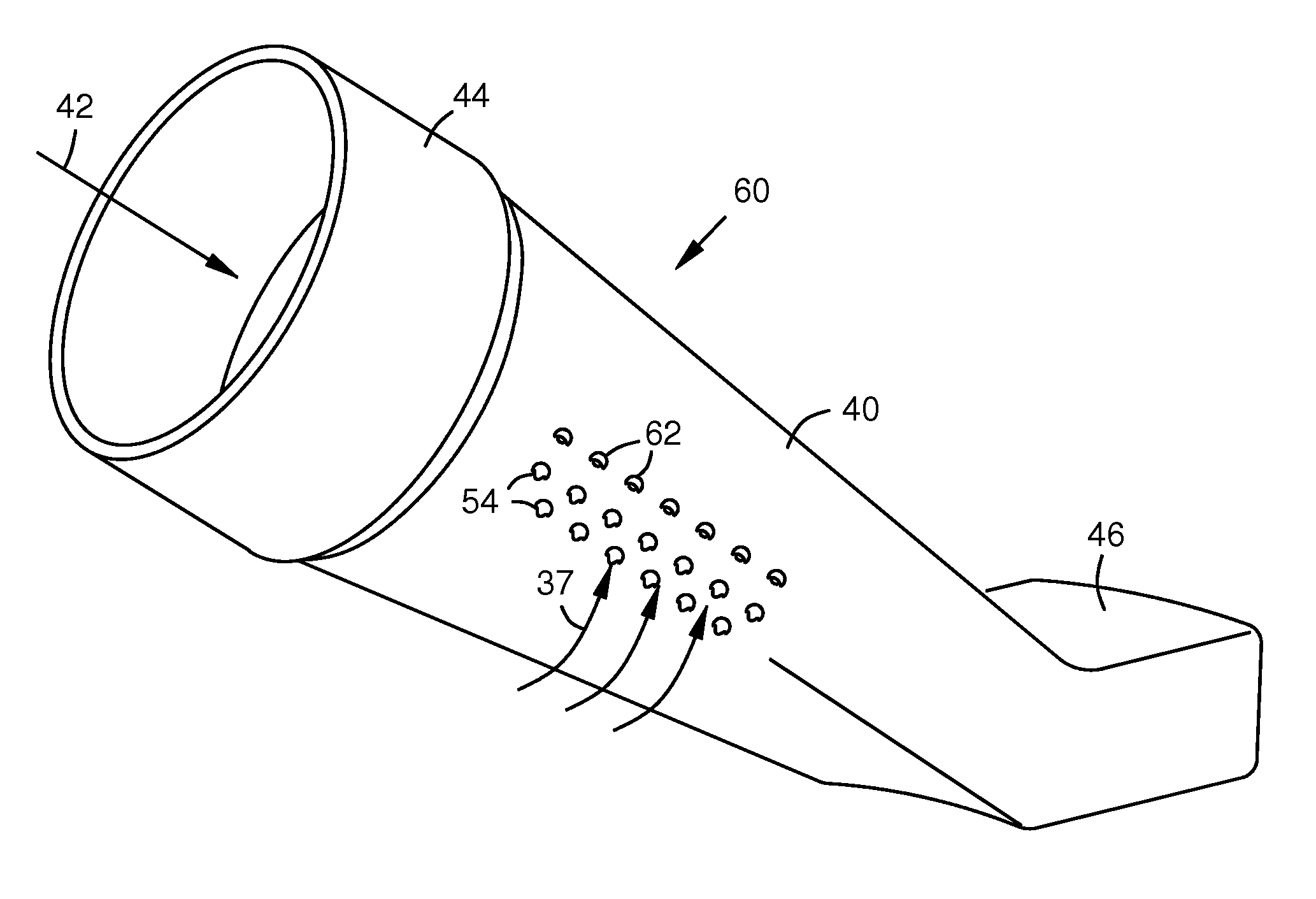
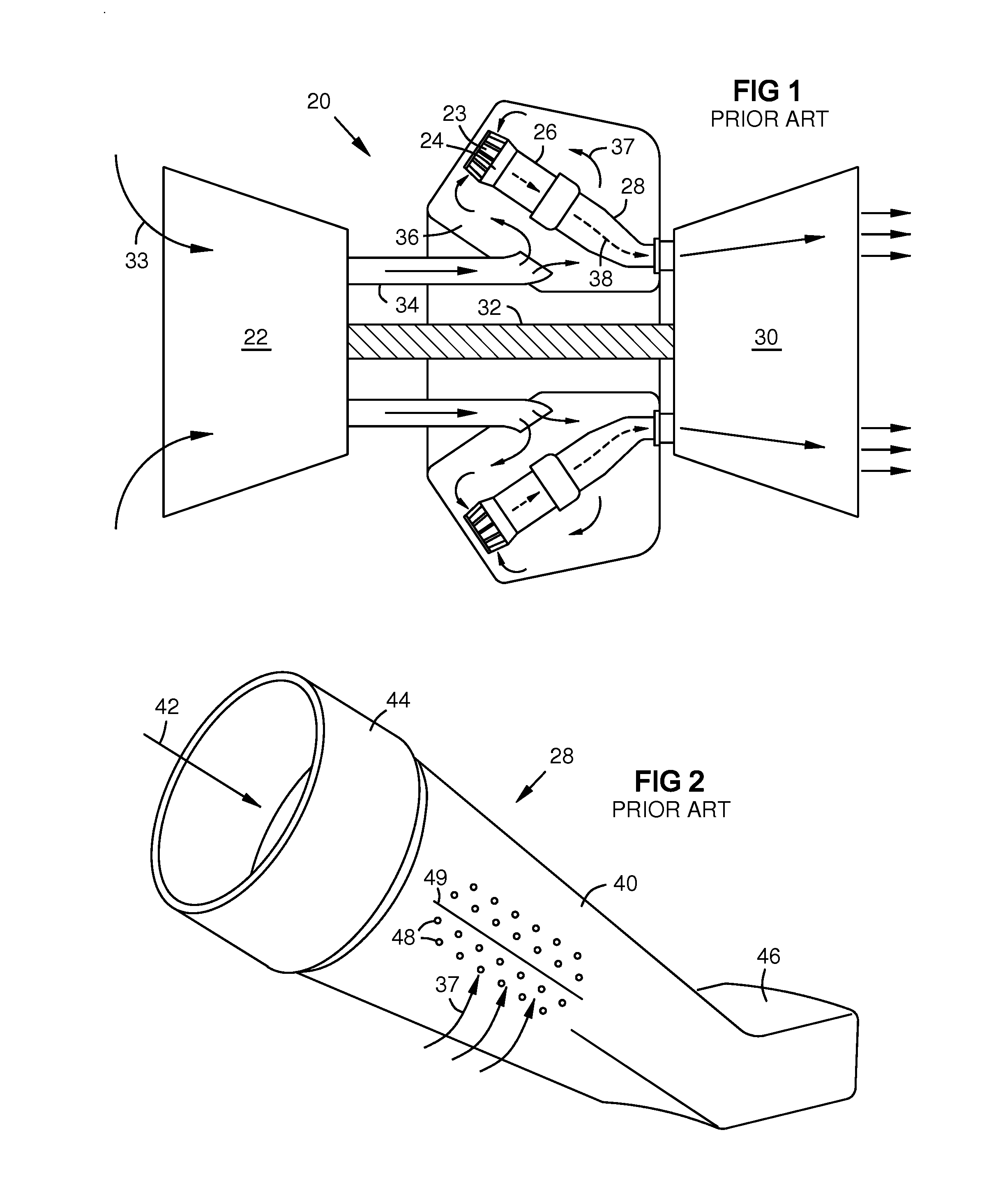
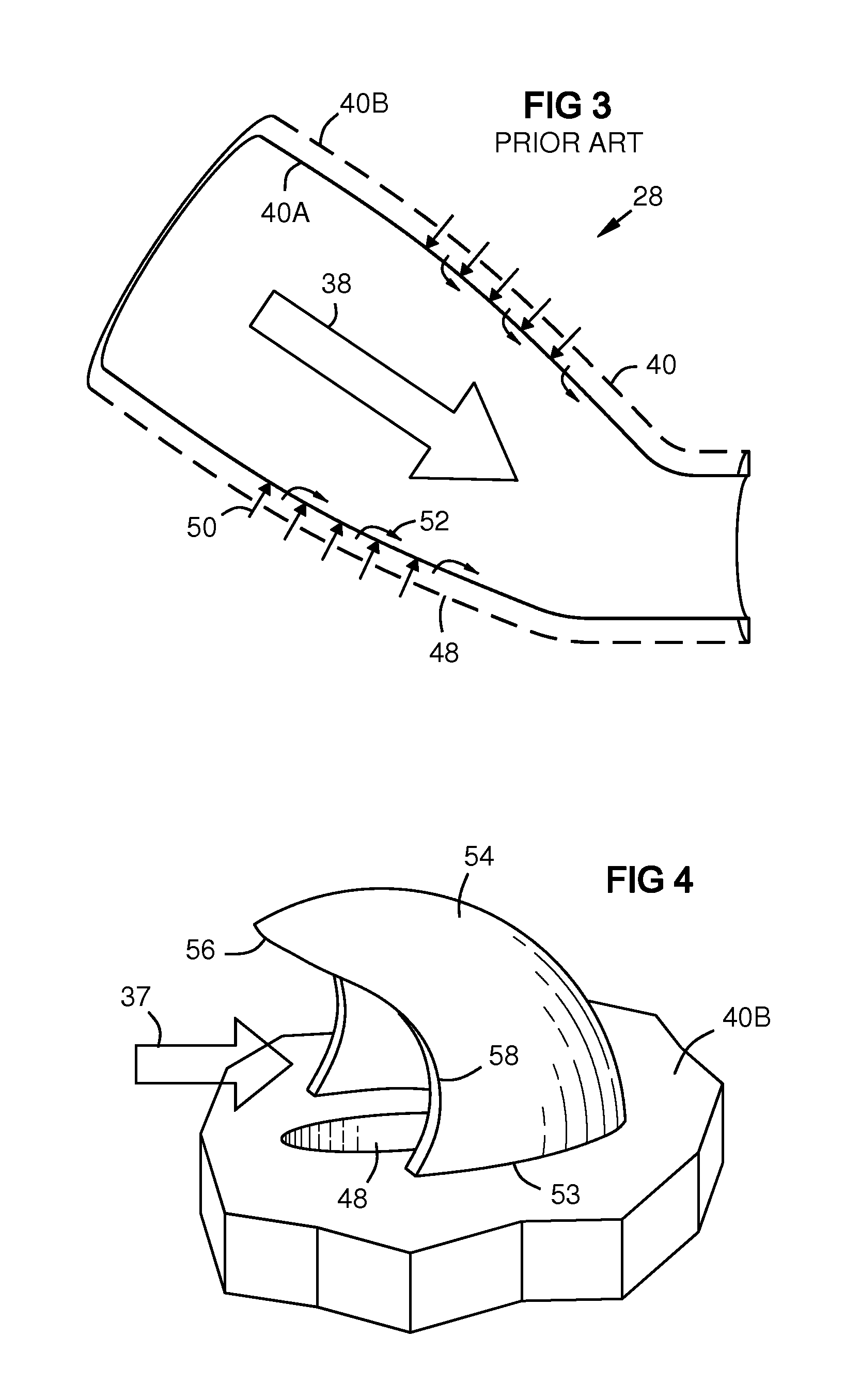
[0017]FIG. 1 is a schematic view of a prior art gas turbine engine 20 that includes a compressor 22, fuel injectors positioned within a cap assembly 24, combustion chambers 26, transition ducts 28, a turbine 30, and a shaft 32 by which the turbine 30 drives the compressor 22. Several combustor assemblies 24, 26, 28 may be arranged in a circular array in a can-annular design known in the art. During operation, the compressor 22 intakes air 33 and provides a flow of compressed air 37 to the combustor inlets 23 via a diffuser 34 and a combustor plenum 36. The fuel injectors within cap assembly 24 mix fuel with the compressed air. This mixture burns in the combustion chamber 26 producing hot combustion gasses 38 that pass through the transition duct 28 to the turbine 30. The diffuser 34 and the plenum 36 may extend annularly about the shaft 32. The compressed airflow 37 in the combustor plenum 36 has higher pressure than the working gas 38 in the combustion chamber 26 and in the transit...


PUM


Abstract

A scoop (54) over a coolant inlet hole (48) in an outer wall (40B) of a double-walled tubular structure (40A, 40B) of a gas turbine engine component (26, 28). The scoop redirects a coolant flow (37) into the hole. The leading edge (56, 58) of the scoop has a central projection (56) or tongue that overhangs the coolant inlet hole, and a curved undercut (58) on each side of the tongue between the tongue and a generally C-shaped or generally U-shaped attachment base (53) of the scoop. A partial scoop (62) may be cooperatively positioned with the scoop (54).

Description

[0001]This application claims benefit of the Mar. 29, 2011 filing date of U.S. patent application Ser. No. 61 / 468,678, which is incorporated by reference herein.FIELD OF THE INVENTION[0002]This invention relates to cooling of gas turbine combustion chambers and transition ducts, and particularly to scoop-assisted impingement cooling.BACKGROUND OF THE INVENTION[0003]In gas turbine engines, air is compressed at an initial stage then heated in combustion chambers. The resulting hot working gas drives a turbine that performs work, including rotating the air compressor.[0004]In a common industrial gas turbine configuration, a number of combustion chambers may be arranged in a circular array about a shaft or axis of the gas turbine engine in a “can annular” configuration. A respective array of transition ducts connects the outflow of each combustor to the turbine entrance. Each transition duct is a generally tubular walled structure or enclosure that surrounds a hot gas path between a com...

Claims


Application Information

Patent Timeline
Patent Type & Authority Applications(United States)
IPC IPC(8): F02C1/00
CPCF01D9/023F05D2250/292F05D2260/201F05B2260/201F05B2250/241F05B2250/292F05D2250/241F01D9/02F01D25/12F23R3/002
Inventor NARCUS, ANDREW R.GENT, MATTHEWTHERRIEN, NEAL
Owner SIEMENS ENERGY INC
Why Eureka
Try Eureka