
Method and Manifold for Carrying Reduced Moment Due to Dimensional Change in Pressure Vessel; Removable Insert with Valve Seat; Pressure Assisted Valve Arrangement and Method

a technology of pressure vessel and manifold, which is applied in the direction of mechanical equipment, transportation and packaging, separation processes, etc., can solve the problems of leakage of valves, loss of production time of the entire process facility, and large number of moving parts which may require maintenance, etc., and achieve the effect of simplifying valve repair and replacemen

Inactive Publication Date: 2012-10-04
LUMMUS TECH INC
View PDF8 Cites 11 Cited by
  • Summary
  • Abstract
  • Description
  • Claims
  • Application Information

AI Technical Summary

Benefits of technology

[0013]One aspect of the present invention provides an insertable valve seat assembly, i.e., an “insert,” that can be used in a PSA valve manifold to simplify valve repair and replacement.
[0015]The insert typically includes the valve seat, thus if the valve seat is damaged, the valve seat can be quickly removed and replaced, minimizing down time of the module containing the damaged valve. Additionally, the insert contains a means to connect the valve bonnet to the insert in a manner that allows the valve body to be easily removed to repair the disc or to replace the entire valve body. In a preferred embodiment the valve body is threaded into the insert. In a preferred embodiment a piston valve is used, however a globe, needle or other valve type could be used.
[0016]The insert is attached directly to the valve manifold by any conventional means creating an easily removable seal to atmosphere. In a preferred embodiment the insert is threaded into the manifold and the seal to atmosphere is made by a radial O-ring seal, cup seal, lip seal or other radial seals. In another preferred embodiment, the use of a two O-rings to create a radial seal is used to limit leakage. The use of more O-rings or the use of a vent or purge at less than process pressure or greater than process pressure between O-rings is also sometimes performed to increase the seal quality and reduce the risk of leaking process gas to atmosphere. The ports in the manifold are separated by any conventional means that allow the insert to be removed. In a preferred embodiment the separation is made by a radial O-ring seal.

Problems solved by technology

Such shutdowns are undesirable as they can cause lost production time for the entire process facility.
While the modular PSA design reduces the single point of failure nature of the conventional PSA design, it still has a large number of moving parts which may require maintenance.
PSA valves typically cycle frequently, and as a result, these valves may incur wear which can potentially lead to a leak in a valve.
Internal leaks occur when the seat or valve member (also referred to as the disc) is damaged resulting in a pathway for gas to flow between the two.
This can affect the purity of the PSA separation thus any leaking valve needs to be repaired quickly.
However, certain disadvantages occur with the system described in FIG. 12.
This displacement can cause stress to connections made to the valve manifold.
In certain cases, leaks or cracks may occur in the plumbing connected to the valve manifold as a result of the displacement caused by the pressure inside the pressure vessel.
One potential problem with the above-noted arrangement is that the valve seat, which is part of the valve manifold, is difficult to rework or service if it should become scratched or otherwise marred.
In some cases, if the valve seat is extensively damaged, the entire valve manifold will have to be replaced merely because the valve seat leaks.
Another potential disadvantage to the system described in FIG. 12 is that the valves are preferably biased to a normally closed position.
However, in sufficiently large valve manifolds, the passages become so large that it is difficult or prohibitively complicated to provide a biasing mechanism that will maintain the valve in a closed state when the pressure inside the plenum cavity is larger than the pressure inside the channel.

Method used


Image

  • Method and Manifold for Carrying Reduced Moment Due to Dimensional Change in Pressure Vessel; Removable Insert with Valve Seat; Pressure Assisted Valve Arrangement and Method
  • Method and Manifold for Carrying Reduced Moment Due to Dimensional Change in Pressure Vessel; Removable Insert with Valve Seat; Pressure Assisted Valve Arrangement and Method
  • Method and Manifold for Carrying Reduced Moment Due to Dimensional Change in Pressure Vessel; Removable Insert with Valve Seat; Pressure Assisted Valve Arrangement and Method

Examples


Embodiment Construction

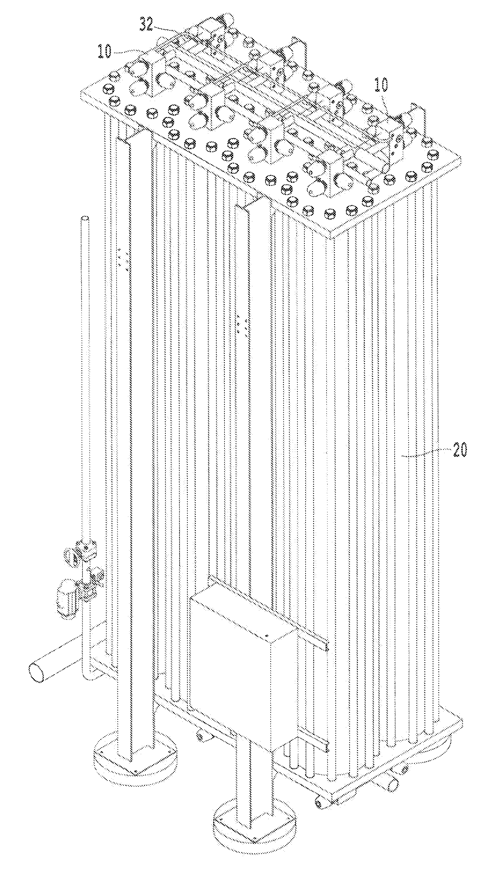
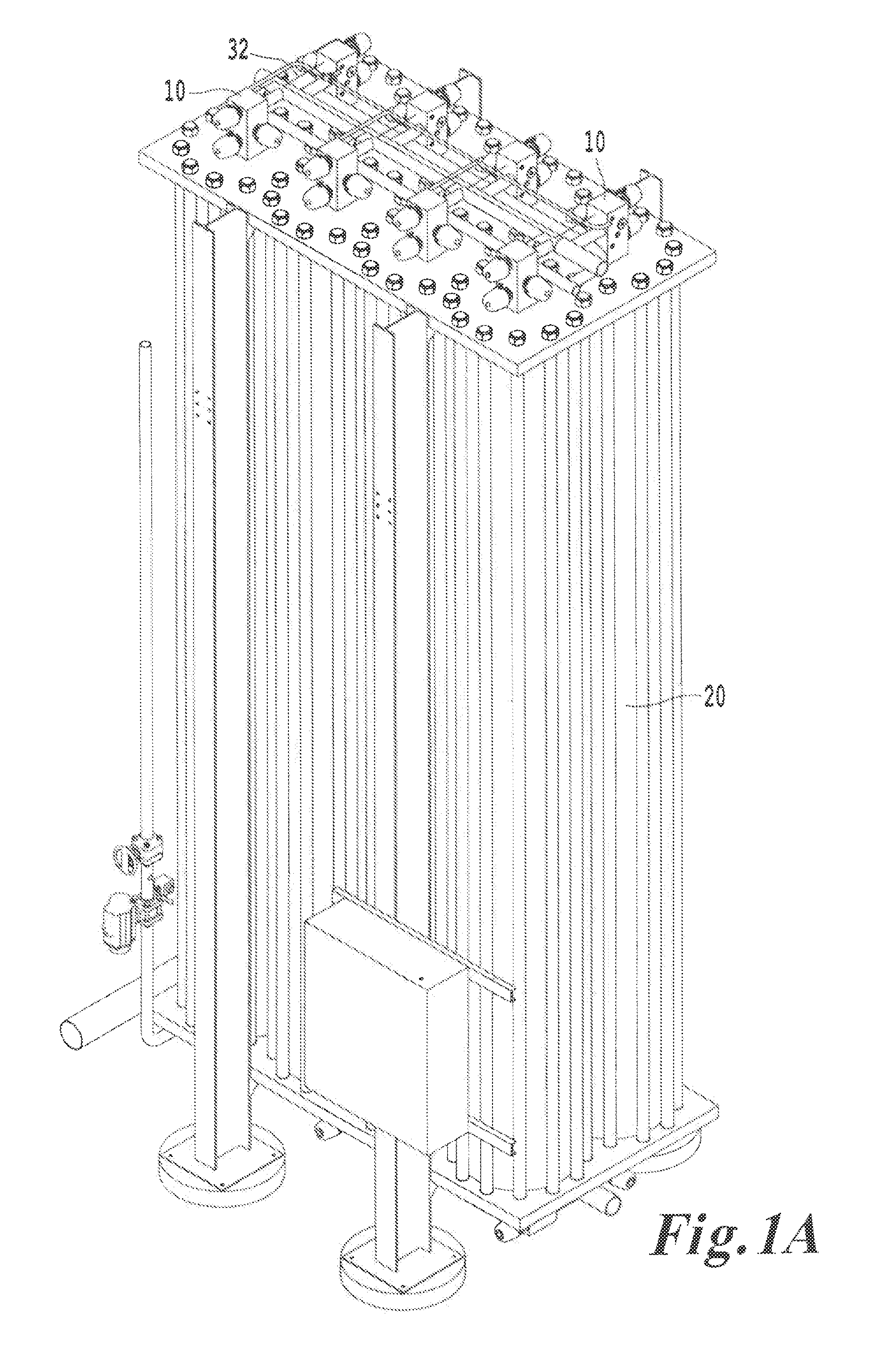
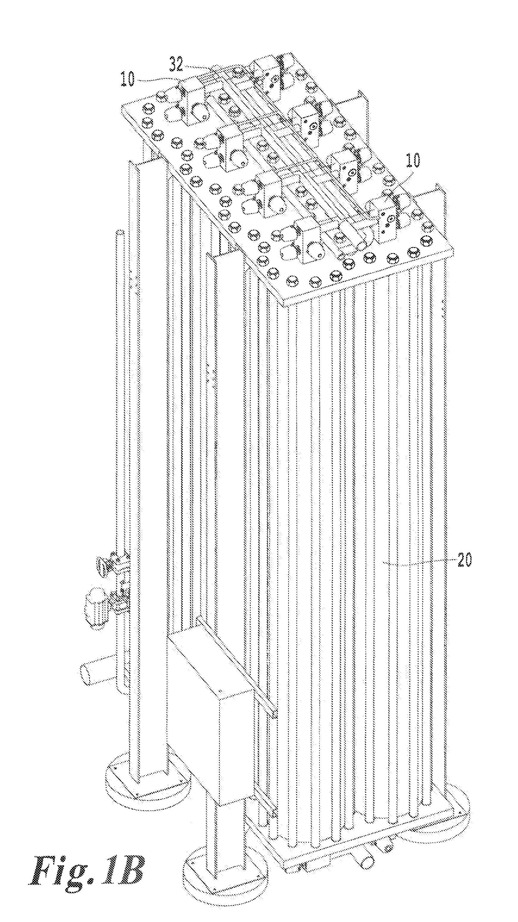
[0051]FIGS. 1A-1B depict various views of a PSA system including four vessels on each side (a total of eight). As shown in FIG. 1B, the various vessels each include a manifold 10 connected via fluid connectors 32. The vessels 20 typically include a manifold 10 on top and on bottom. The manifolds 10 can be identical or differently ported, depending on the use of the PSA system.

[0052]FIG. 2 depicts four adsorbent vessels 20 forming a PSA system. In FIG. 3, each valve manifold 10 is provided with two valves 31. However, arrangements with three, four, or more valves may be used. The valve manifold may be manufactured by machining, casting, forging, or powdered metallurgy, for example. Typical materials for the manifold 10 are carbon steel or stainless steel, but other materials may be used. Each fluid channel can communicate with every other vessel via fluid connectors 32. The fluid connectors 32 can be rigid pipes as shown here, or may be compliant, flexible tubing. Further, the fluid ...


PUM


Abstract

A pressure swing adsorption system includes a pressure vessel, a nozzle plate coupled to the vessel and sealed with respect to the pressure vessel, a backing plate that supports the nozzle plate, and a manifold including a plenum cavity and coupled to the nozzle plate via a neck such that the plenum cavity is in fluid communication with an interior of the pressure vessel. The neck is sealed with respect to the nozzle plate via a movable sealing surface. A method is provided in which pressure from the plenum cavity assists in closing valve coupled to the manifold. A removable insert is provided to the manifold to provide a removable sealing surface against which the valve closes.

Description

BACKGROUND OF THE INVENTION[0001]1. Field of the Invention[0002]This invention relates to methods, devices, and systems for making and controlling connections to industrial pressure vessels. In one example, the invention relates to a removable insert for valve manifold that connects to pressure vessel. Another example relates to a valve manifold that applies pressure to a closing portion of a valve so as to assist in closing the valve against a seat. Another example relates to a manifold connection that reduces or prevents dimensional changes in a portion of a pressure vessel or a part connected to a pressure vessel from transmitting force or moment to a nozzle connection. In certain examples, the above-noted arrangements relate to use in pressure swing adsorption (PSA) apparatuses.[0003]2. Description of the Related Art[0004]Early PSA systems generally used four adsorbent vessels operated in parallel. An example of such a PSA system is described in U.S. Pat. No. 3,430,418 to Wagner...

Claims


Application Information

Patent Timeline
Patent Type & Authority Applications(United States)
IPC IPC(8): B01D53/047F16K51/00
CPCB01D53/0407B01D53/047B01D53/0446B01D2259/4065B01D2259/404Y10T137/0491
Inventor LOMAX, JR., FRANKLIN D.ABRAMOWITZ, HOWARDMCCULLOUGH, EDWARD T.
Owner LUMMUS TECH INC
Learn More