Electrode having gas discharge function and plasma processing apparatus

a technology of plasma processing apparatus and electrode, which is applied in the direction of discharge tube/lamp details, discharge tube main electrodes, discharge tube materials, etc., can solve the problems of gas hole at the processing space damage, limited degree of freedom related to the maximum gas flow rate, and inability to reduce manufacturing costs

Active Publication Date: 2012-10-04
TOKYO ELECTRON LTD
View PDF33 Cites 36 Cited by
  • Summary
  • Abstract
  • Description
  • Claims
  • Application Information

AI Technical Summary

Benefits of technology

[0013]The present invention provides an electrode having a gas discharge function, where the degree of freedom related to a maximum gas flow rate is abundant, an electrode cover member may ...

Problems solved by technology

Accordingly, an electrode cover member cannot be thinned, and thus reduction of manufacturing costs is hindered and the deg...

Method used


Image

  • Electrode having gas discharge function and plasma processing apparatus
  • Electrode having gas discharge function and plasma processing apparatus
  • Electrode having gas discharge function and plasma processing apparatus

Examples


first embodiment

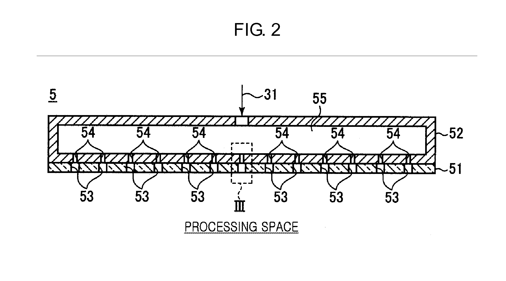
[0052]FIG. 3 is a magnified view of an example of an inside of a broken line frame III of FIG. 2, according to a first embodiment of an electrode having a gas discharge function.

[0053]As shown in FIG. 3, in the present embodiment, a gas hole diameter φA of the gas hole 53 of the electrode cover member 51 is larger than a gas hole diameter φB of the gas hole 54 of the base material 52. For example, the gas hole diameter φA exceeds the gas hole diameter φB and less than or equal to three times of the gas hole diameter φB.

[0054]The reason why the gas hole diameter φA exceeds the gas hole diameter φB is to increase conductance of the gas hole 53 of the electrode cover member 51 higher than conductance of the gas hole 54 of the base material 52. As such, by setting the conductance of the gas hole 53 of the electrode cover member 51 higher than the conductance of the gas hole 54 of the base material 52, a differential pressure (stress) due to the processing gas is not applied to the elect...

second embodiment

[0062]FIG. 4 is a magnified view of an example of the inside of the broken line frame III of FIG. 2, according to a second embodiment of an electrode having a gas discharge function.

[0063]The coating film 57 may be formed throughout a side wall from a bottom of the clearance portion 56 having the concave shape as shown in FIG. 3, or may be formed only at the bottom of the clearance portion 56 having the concave shape as shown in FIG. 4.

[0064]Also, when the coating film 57 is formed by, for example, spraying, the coating film 57 may be formed inside the gas hole 54 near an outlet of the gas hole 54 communicating with the clearance portion 56, as shown in FIG. 4. The coating film 57 may be also formed inside the gas hole 54. When the coating film 57 is formed inside the gas hole 54 near the outlet, the vicinity of the outlet of the gas hole 54 may also be protected from plasma.

third embodiment

[0065]FIG. 5 is a magnified view of an example of the inside of the broken line frame III of FIG. 2, according to a third embodiment of an electrode having a gas discharge function.

[0066]Alternatively, as shown in FIG. 5, a depth D1 of an outer circumference of the clearance portion 56 may be shallower than a depth D2 of an inner side of the clearance portion 56. As such, by setting the depth D1 of the outer circumference of the clearance portion 56 shallower than the depth D2 of the inner side, it may be difficult for plasma that deeply entered the inside of the clearance portion 56 to reach the side wall of the clearance portion 56. Such a benefit is specifically useful, for example, in a structure where the coating film 57 does not exist on the side wall of the clearance portion 56.

[0067]Also, as shown in FIGS. 4 and 5, a chamfered portion 58 having a tapered shape may be formed at a surface of the gas hole 53 of the electrode cover member 51 attached to the base material 52, whe...


PUM

PropertyMeasurementUnit
Thicknessaaaaaaaaaa
Thicknessaaaaaaaaaa
Diameteraaaaaaaaaa

Abstract

An electrode having a gas discharge function, where the degree of freedom related to a maximum gas flow rate is abundant, an electrode cover member may be thinned, and a change of a gas behavior according to time is difficult to be generated in a processing chamber during gas introduction. The electrode includes: a base material having a plurality of gas holes; and an electrode cover member having a plurality of gas holes respectively corresponding to the plurality of gas holes of the base material in a one-to-one manner, fixed to the base material, and disposed facing a processing space in which the object is plasma-processed, wherein a gas hole diameter of the electrode cover member is larger than a gas hole diameter of the base material.

Description

CROSS-REFERENCE TO RELATED PATENT APPLICATIONS[0001]This application claims the benefit of Japanese Patent Application No. 2011-078214 filed on Mar. 31, 2011 in the Japan Patent Office, U.S. Patent Application No. 61 / 477,183 filed on Apr. 20, 2011 in the U.S. Patent and Trademark Office, and Japanese Patent Application No. 2012-073431 filed on Mar. 28, 2012 in the Japan Patent Office, the disclosures of which are incorporated herein in their entireties by reference.BACKGROUND OF THE INVENTION[0002]1. Field of the Invention[0003]The present invention relates to an electrode having a gas discharge function and a plasma processing apparatus.[0004]2. Description of the Related Art[0005]A plasma process, such as a plasma etching process or a plasma chemical vapor deposition (CVD) process, is used to manufacture a semiconductor integrated circuit apparatus. A typical plasma processing apparatus includes an upper electrode and a lower electrode in a processing chamber, and plasmatizes a pr...

Claims


Application Information

Patent Timeline
IPC IPC(8): H01J1/02H05H1/24B44C1/22C23C16/50C23C16/455
CPCH01J37/32449H01J1/02H01J37/32532C23C16/455C23C16/45563C23C16/45565C23C16/45576C23C16/50C23C16/503C23C16/505C23C16/509C23F1/12H01J1/00
Inventor HAYASHI, DAISUKEISHIDA, TOSHIFUMIAMIKURA, NORIHIKO
Owner TOKYO ELECTRON LTD
Why Eureka
Try Eureka