Traveling wave amplifier with pre-emphasis function

a technology of amplifiers and functions, applied in amplifiers, amplifiers with coupling networks, amplifiers with semiconductor devices/discharge tubes, etc., can solve the problems of shortening the rise and fall edges, overshooting and undershooting, and the difference between two delays, so as to enhance the optical characteristic of the output of the device

Active Publication Date: 2012-10-04
SUMITOMO ELECTRIC IND LTD
View PDF3 Cites 5 Cited by
  • Summary
  • Abstract
  • Description
  • Claims
  • Application Information

AI Technical Summary

Benefits of technology

[0010]Another aspect according to an embodiment of the present invention relates to a driver circuit using the TWA above described. The driver circuit of the embodiment is particularly adequate to drive a semiconductor optical device, such as a semiconductor laser diode and/or a semiconductor opt

Problems solved by technology

The TWA thus configured causes overshoot and undershoot in the output thereof but may shorten the rising and falling edges thereof.
The inserted

Method used


Image

  • Traveling wave amplifier with pre-emphasis function
  • Traveling wave amplifier with pre-emphasis function
  • Traveling wave amplifier with pre-emphasis function

Examples


Embodiment Construction

[0022]Next, some preferred embodiments according to the present invention will be described as referring to drawings. In the description of the drawings, the same elements will be referred by the numerals or symbols same to each other without overlapping explanations.

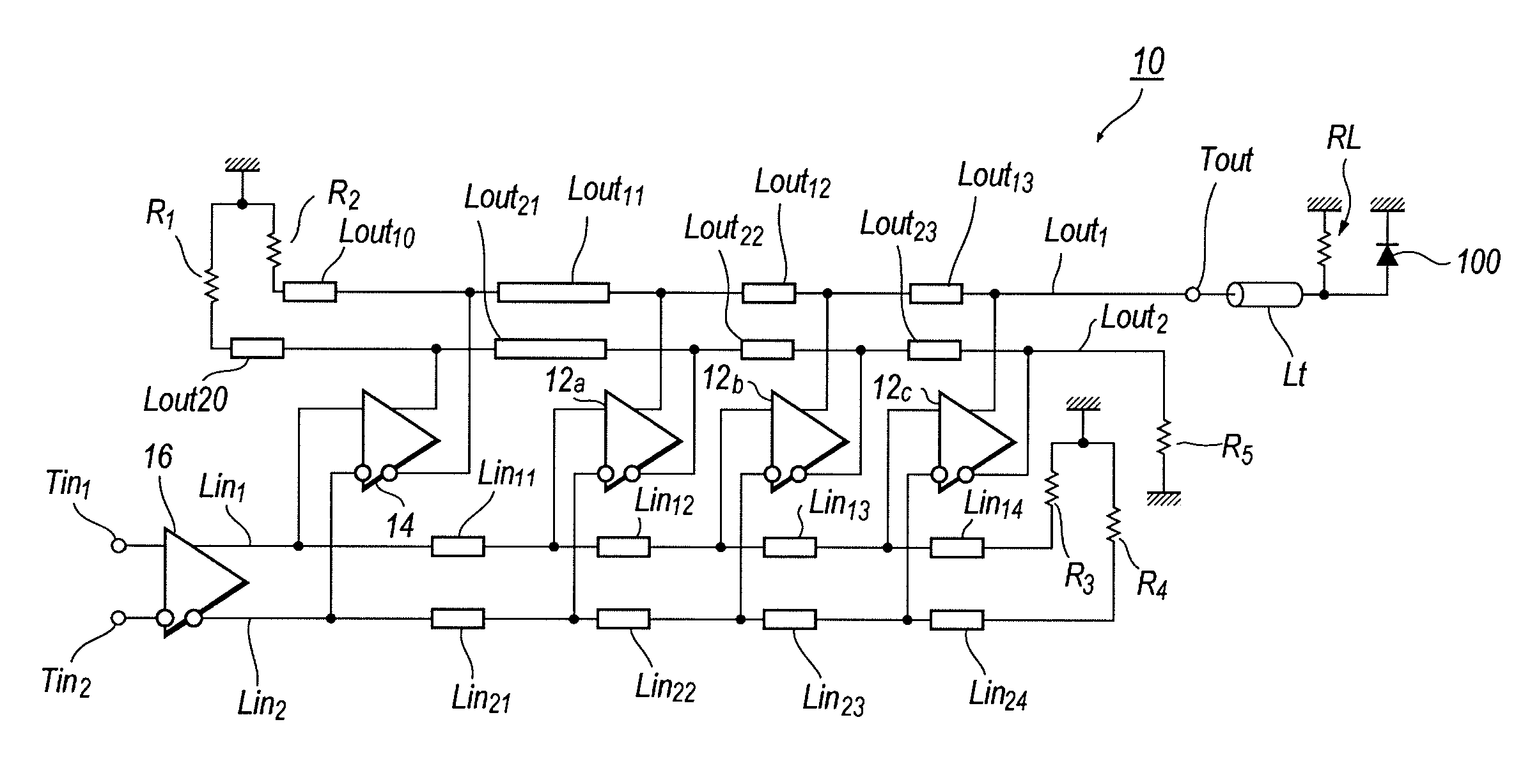
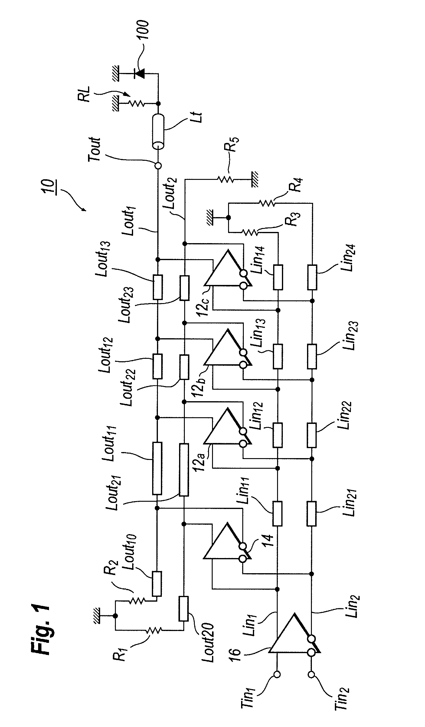
[0023]FIG. 1 is a circuit diagram of a differential traveling wave amplifier (TWA) according to an embodiment of the invention. The TWA 10 is circuit applicable to drive an optical modulator 100, which is, for instance, an electro-absorption (EA) modulator. The EA modulator 100 shown in FIG. 1 is connected in parallel to a load resistor RL to terminate the transmission line Lt. The parallel circuit of the resistor RL and the EA modulator 100 is connected in an output Tout of the TWA 10 through the transmission line Lt.

[0024]The TWA 10 includes an array of differential circuits, 12a to 12c, of the first type, and another differential circuit 14 of the second type. The TWA 10 also provides input transmission lines, Lin1 a...


PUM


Abstract

A traveling wave amplifier (TWA) primarily for driving a semiconductor optical device is disclosed. The TWA of an embodiment provides a plurality of differential amplifiers of the first type and an additional differential amplifier of the second type, where are they are connected between the input and the output of the TWA. The differential amplifiers of the first type provide a first delay from the input to the output, while, the differential amplifier of the second type provide a second delay longer than the first delay between the input and the output of the TWA.

Description

BACKGROUND OF THE INVENTION[0001]1. Field of the Invention[0002]The present invention relates to a traveling wave amplifier (hereafter denoted as TWA) to drive, for instance, an optical modulator.[0003]2. Related Background Art[0004]Various types of TWAs have been disclosed in, for instance, Japanese Patent Applications published as JP-H10-510970, JP-2003-304131A, JP-2006-054765A, and / or United States patents, U.S. Pat. No. 5,550,513 and U.S. Pat. No. 7,368,997. A TWA ordinarily provides a plurality of amplifiers connected in parallel between input transmission lines and output transmission lines. An output of the TWA adds outputs of respective amplifiers by aligning their phases, or a delay from the input terminal to the output terminal, at the output terminal of the TWA.[0005]When such a TWA is applied to be used as a driver, for instance, to drive an optical modulator or a semiconductor laser diode, the optical output provided from the optical modulator, or the laser diode, makes...

Claims


Application Information

Patent Timeline
IPC IPC(8): H03F3/60
CPCH03F3/45089H03F3/45475H03F2203/45612H03F2203/45138H03F2203/45392H03F3/605
Inventor TATSUMI, TAIZOUTANAKA, KEIJISAWADA, SOSAKU
Owner SUMITOMO ELECTRIC IND LTD
Why Eureka
Try Eureka