
Magnetic-dielectric assembly

a technology of dielectric assembly and dielectric assembly, which is applied in the direction of magnetic bodies, magnetic materials, electrical equipment, etc., can solve the problems of reducing the overall surface smoothness, affecting the performance of devices such as isolators, reducing the thickness variation of the cut magnetic-dielectric assembly, etc., and achieves the effect of reducing the high frequency magnetic and/or electric loss tangent, high thermal conductivity, and heating and swelling of the adhesiv

Inactive Publication Date: 2012-10-04
ALLUMAX TTI LLC
View PDF10 Cites 3 Cited by
  • Summary
  • Abstract
  • Description
  • Claims
  • Application Information

AI Technical Summary

Benefits of technology

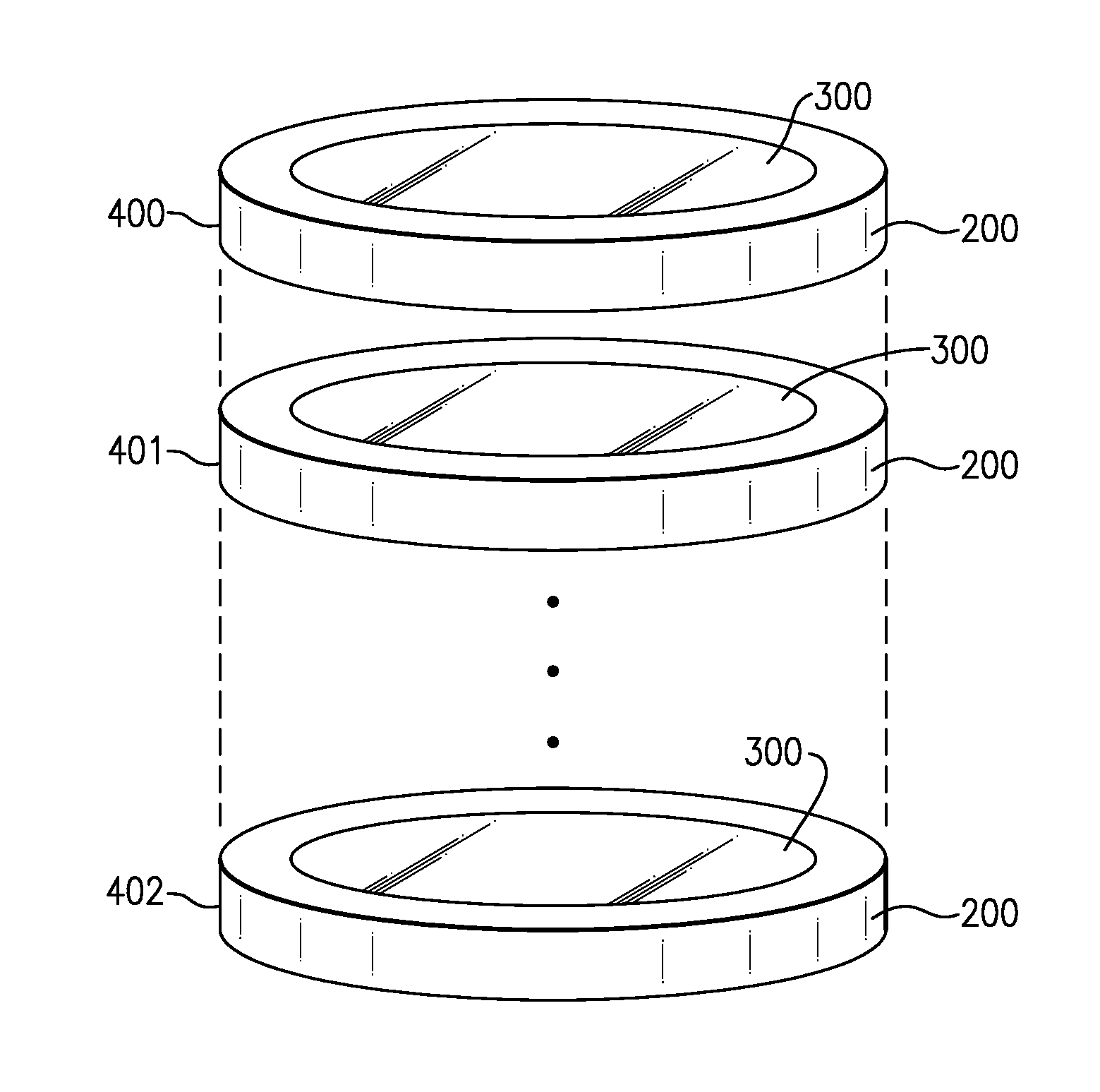
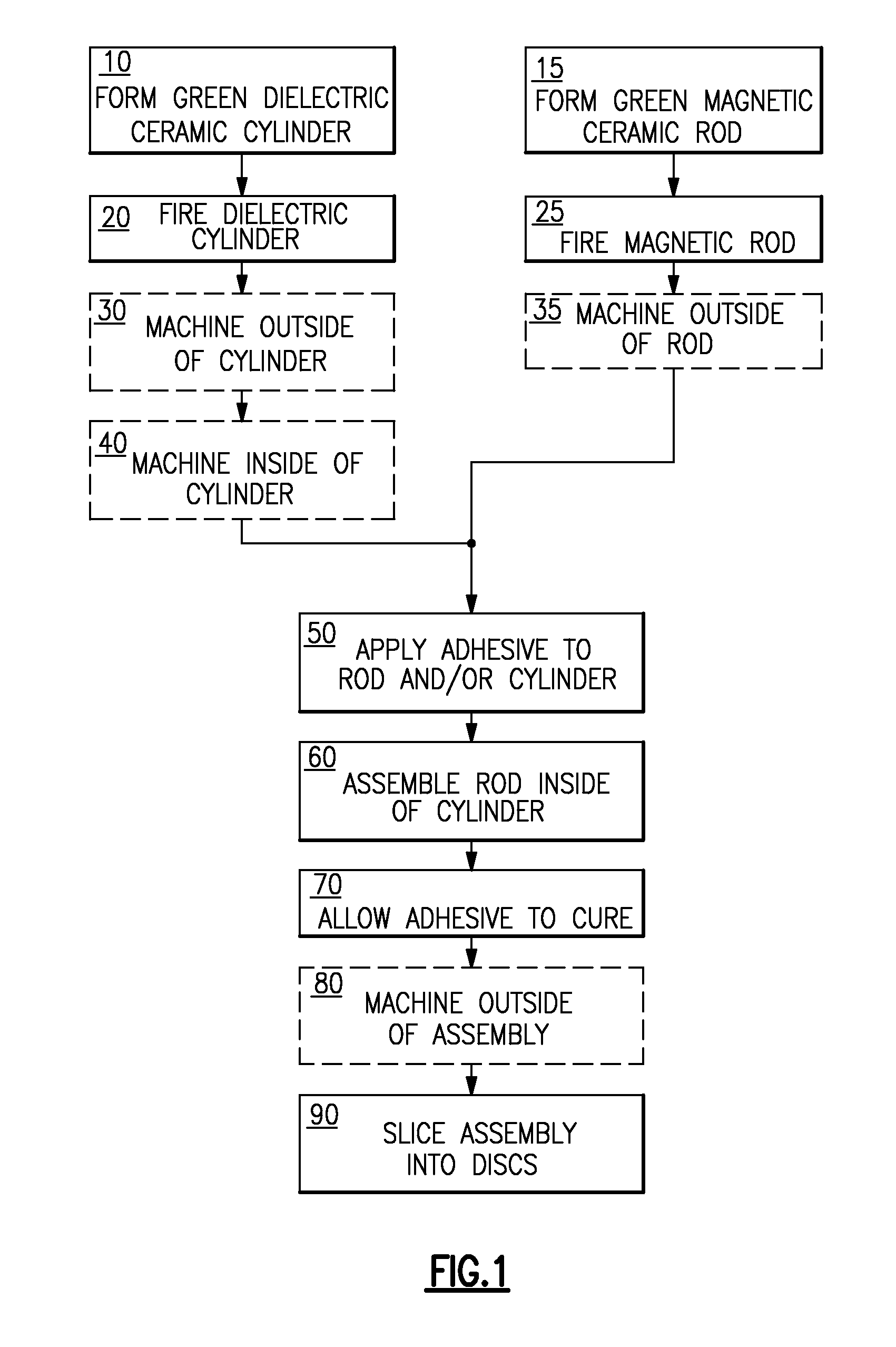
"The patent describes a magnetic-dielectric assembly that includes a magnetic ceramic disc and a dielectric ceramic ring joined by an adhesive. The adhesive includes particles of a material with high thermal conductivity, which helps to reduce heating and swelling during cutting of the assembly. The adhesive also has a lower dielectric constant and lower thermal conductivity than conventional epoxy, which improves performance in high frequency applications. The assembly can be used in electrical devices such as circulators and isolators, and the thickness of the assembly is between 1 millimeter and 10 millimeters. The use of the powdered ceramic in the adhesive results in a decrease in insertion loss and an increase in yield of parts from the assembly. The adhesive also helps to facilitate machining of the assembly to size. Overall, the technical effects of the patent include improved performance and yield of parts from the magnetic-dielectric assembly."

Problems solved by technology

Assemblies using organic adhesives often heat up during machining, causing the adhesive to swell at the cut surface, producing a surface bump and reducing overall surface smoothness, which may affect the performance of devices such as isolators.
In addition, softened adhesive may in some cases adhere to portions of the cutting blade, causing it to flex or bend, also reducing the smoothness and / or increasing the variation in thickness of the cut magnetic-dielectric assemblies.
Many organic adhesives have a significant high frequency magnetic and / or electric loss tangent.
However, co-fired assemblies are not possible for all combinations of dielectric and magnetic materials because of differences in thermal expansion between the two materials.

Method used


Image

  • Magnetic-dielectric assembly
  • Magnetic-dielectric assembly
  • Magnetic-dielectric assembly

Examples


Embodiment Construction

[0035]It is to be appreciated that embodiments of the materials, methods, and apparatuses discussed herein are not limited in application to the details of construction and the arrangement of components set forth in the following description or illustrated in the accompanying drawings. The materials, methods, and apparatuses are capable of implementation in other embodiments and of being practiced or of being carried out in various ways. Examples of specific implementations are provided herein for illustrative purposes only and are not intended to be limiting. In particular, acts, elements, and features discussed in connection with any one or more embodiments are not intended to be excluded from a similar role in any other embodiments. Also, the phraseology and terminology used herein is for the purpose of description and should not be regarded as limiting. The use herein of “including,”“comprising,”“having,”“containing,”“involving,” and variations thereof is meant to encompass the ...


PUM

PropertyMeasurementUnit
median diameteraaaaaaaaaa
thicknessaaaaaaaaaa
thicknessaaaaaaaaaa

Abstract

A magnetic-dielectric disc assembly includes a magnetic ceramic disc coaxially secured within a dielectric ceramic ring by an adhesive that includes a powdered ceramic in an epoxy matrix. The powdered ceramic is selected from the group consisting of alumina, titania, silica, and zirconia. The magnetic-dielectric disc assembly can be used as a component of, for example, a circulator, isolator, or similar electrical assembly.

Description

CROSS-REFERENCE TO RELATED APPLICATIONS[0001]This application is a division of U.S. patent application Ser. No. 13 / 087,975, titled “MAGNETIC-DIELECTRIC ASSEMBLIES AND METHODS OF FABRICATION,” filed on Apr. 15, 2011, which is a continuation of International Patent Application Serial No. PCT / US2008 / 086969, filed Dec. 16, 2008 which claims priority to U.S. Provisional Patent Application Ser. No. 61 / 106,841, titled “MAGNETIC-DIELECTRIC ASSEMBLIES AND METHODS OF FABRICATION,” filed on Oct. 20, 2008, each of which is herein incorporated by reference in its entirety for all purposes.BACKGROUND OF INVENTION[0002]1. Field of Invention[0003]The present invention is directed to materials and methods for forming ceramic assemblies with adhesive materials having desirable magnetic, abrasive, and thermal properties.[0004]2. Discussion of Related Art[0005]Circulators and isolators are passive electric devices that are used in radio frequency (RF) systems, for example, microwave systems, to permit ...

Claims


Application Information

Patent Timeline
Patent Type & Authority Applications(United States)
IPC IPC(8): H01F1/00
CPCY10T156/1052H01P1/387H01P1/36H01P1/38
Inventor CRUICKSHANK, DAVELY, TRI M.ZHENG, JINGMIN
Owner ALLUMAX TTI LLC
Learn More