

Polarization beam splitting element and image projection apparatus
- Summary
- Abstract
- Description
- Claims
- Application Information
AI Technical Summary
Benefits of technology
Problems solved by technology
Method used
Image

Examples
embodiment 1
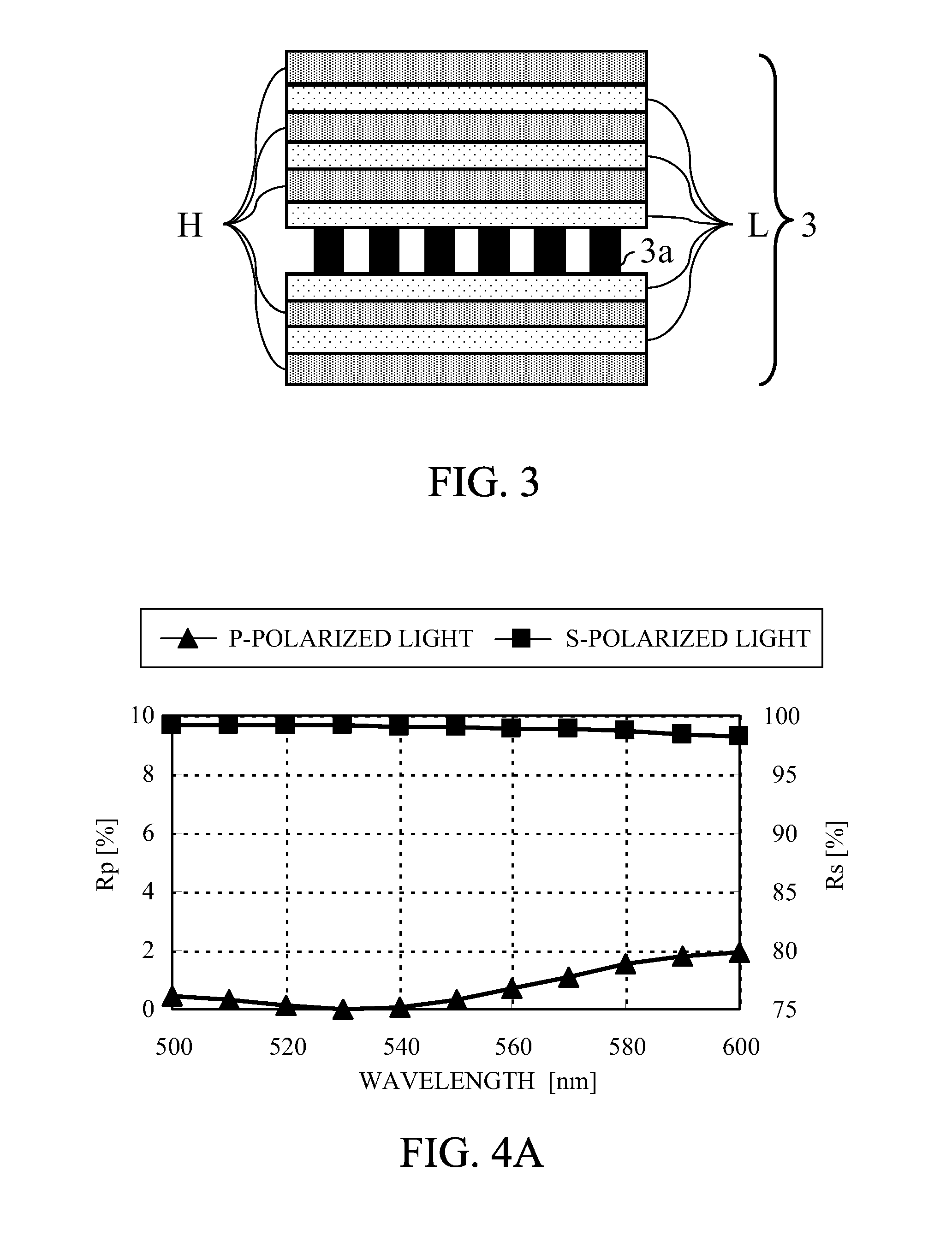
[0058]FIG. 3 shows a configuration of a polarization beam splitting part 3 of a polarization beam splitting element that is a first embodiment (Embodiment 1) of the present invention. Prisms (not shown, but corresponding to the prisms 1 and 2 shown in FIG. 1) have a refractive index of 1.75. An entrance side multi-layered film layer and an exit side multi-layered film layer (respectively corresponding to the entrance side and exit side multi-layered film layers 3c and 3b shown in FIG. 2A) are each constituted by two types of layers, that is, H and L layers alternately disposed, the H layer having a higher refractive index than that of the prism (2) and the L layer having a lower refractive index than that of the prism (2).
[0059]Specifically, the polarization beam splitting part 3 in this embodiment has a configuration including, in order from its beam entrance side, HLHLHL-wire grid-LHLH. In each of the entrance side and exit side multi-layered film layers, a dielectric film adjacen...
embodiment 2
[0079]FIG. 5 shows a configuration of a polarization beam splitting part 3 of a polarization beam splitting element that is a second embodiment (Embodiment 2) of the present invention. Also in this embodiment, a refractive index of two prisms (not shown, but similar to the prisms 1 and 2 in Embodiment 1) is 1.75.
[0080]The polarization beam splitting part 3 has a configuration including, when a dielectric film having a higher refractive index than that of the prism (2) as an entrance medium is denoted by “H” and a dielectric film having a lower refractive index than that of the entrance medium is denoted by “L”, in order from its beam entrance side, HLHL-(wire grid)-LHLH. Table 2 shows refractive indices and thicknesses of the respective layers. The wire grid 3a is formed of aluminum. In the wire grid 3a, a grating thickness is 18 nm, a filling factor FF is 0.40, and a grating period is 100 nm. A medium forming inter-grating portions is air.
[0081]FIG. 6A shows reflectances of the pol...
embodiment 3
[0084]FIG. 7 shows a configuration of a polarization beam splitting part 3 of a polarization beam splitting element that is a third embodiment (Embodiment 3) of the present invention. Also in this embodiment, a refractive index of two prisms (not shown, but similar to those in Embodiment 1) is 1.75.
[0085]The polarization beam splitting part 3 has a configuration including, in order from its beam entrance side, HLHLHL-(wire grid)-LHLH. Table 3 shows refractive indices and thicknesses of the respective layers. The wire grid 3a is formed of aluminum. In the wire grid 3a, a grating thickness is 32 nm, a filling factor FF is 0.37, and a grating period is 100 nm. A medium forming inter-grating portions is a same dielectric material as that forming the L layer.
[0086]FIG. 8A shows reflectances of the polarization beam splitting part 3 for the s-polarized light and the p-polarized light at various wavelengths when an entering beam enters an entrance surface of the prism (2) perpendicularly t...
PUM
 Abstract
Description
Claims
Application Information