Apparatus and Method to Adjust Clock Duty Cycle of Memory

a clock duty cycle and memory controller technology, applied in the field of memory controllers, can solve problems such as inability to achieve optimal timing margin, data acquired by dram controllers may be faulty, and dram controllers may not acquire the correct signal

Active Publication Date: 2012-10-04
MEDIATEK INC
View PDF6 Cites 56 Cited by
  • Summary
  • Abstract
  • Description
  • Claims
  • Application Information

AI Technical Summary

Problems solved by technology

The sampling signal DQS is generated based on the clock signal and if the quality of the clock signal, such as the duty cycle, is not good enough, the data acquired by the DRAM controller may be faulty.
Accordingly, the DRAM controller may not acquire the correct signal DQ and an optim...

Method used


Image

  • Apparatus and Method to Adjust Clock Duty Cycle of Memory
  • Apparatus and Method to Adjust Clock Duty Cycle of Memory
  • Apparatus and Method to Adjust Clock Duty Cycle of Memory

Examples


Embodiment Construction

[0023]The following description is of the best-contemplated mode of carrying out the invention. This description is made for the purpose of illustrating the general principles of the invention and should not be taken in a limiting sense. The scope of the invention is best determined by reference to the appended claims.

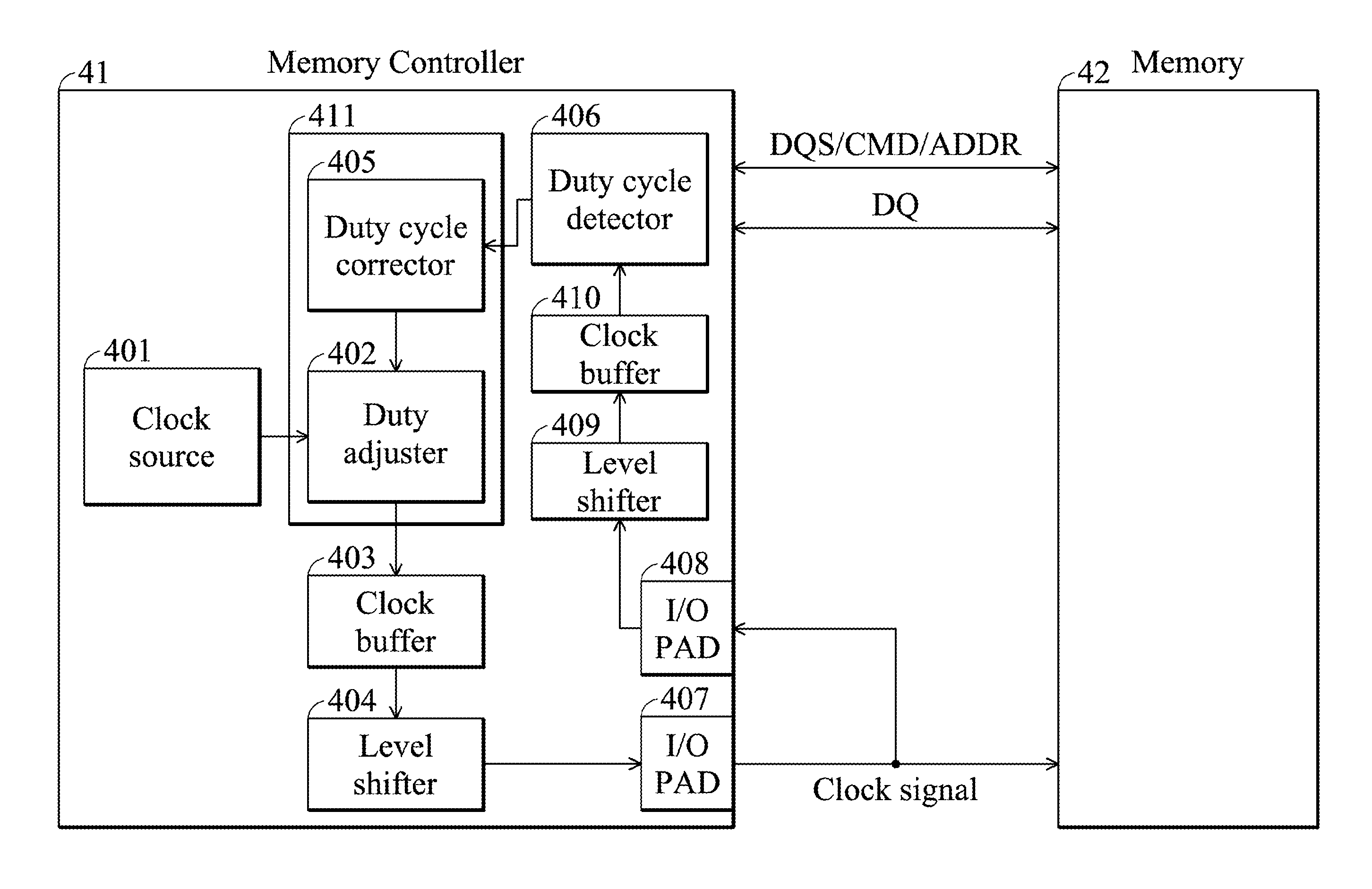
[0024]FIG. 3 is a block diagram of a memory system with a clock duty cycle adjusting mechanism according to one embodiment of the invention. The memory controller 41 includes a clock source 401, a duty cycle calibration device 411, a clock buffer 403, a level shifter 404, a duty cycle detector 406, an I / O pad 407, an I / O pad 408, a level shifter 409 and a clock buffer 410. The duty cycle calibration device 411 further comprises a duty cycle corrector 405 and a duty adjuster 402. The memory controller 41 is for controlling the memory 42. The memory 42 may be a dynamic random access memory (DRAM), flash memory or any other type of memory requiring clock duty cycle accura...


PUM


Abstract

An embodiment of the invention provides a memory controller for controlling a memory. The memory controller comprises a pulse width modulation module, a voltage comparator and a duty cycle calibration device. The pulse width modulation module is suitable for receiving a clock signal to generate a first voltage. The voltage comparator is suitable for receiving and comparing a reference voltage with the first voltage to output a comparison signal. The duty cycle calibration device is suitable for adjusting a duty cycle of the clock signal according to the comparison signal.

Description

BACKGROUND OF THE INVENTION[0001]1. Field of the Invention[0002]The invention relates to a memory controller, and more particularly, to a memory controller with a clock duty cycle adjusting mechanism.[0003]2. Description of the Related Art[0004]When a dynamic random access memory (DRAM) controller accesses a DRAM, the DRAM controller transmits a clock signal to the DRAM and the DRAM sends back a DQS signal to the DRAM controller for sampling the data signal DQ. The sampling signal DQS is generated based on the clock signal and if the quality of the clock signal, such as the duty cycle, is not good enough, the data acquired by the DRAM controller may be faulty.[0005]FIG. 1 is a timing diagram showing a DDR DRAM read operation with a balanced clock duty cycle. In FIG. 1, the duty cycle of the clock signal transmitted to the DRAM is 50%, such that the signal DQS is driven by the clock signal with a duty cycle of 50%. Accordingly, an optimal timing margin is achieved.[0006]FIG. 2 is a t...

Claims


Application Information

Patent Timeline
IPC IPC(8): G11C7/06G11C7/00G11C8/18
CPCG11C7/1066G11C11/409G11C29/50012G11C29/028
Inventor HUANG, HSIANG-I
Owner MEDIATEK INC
Why Eureka
Try Eureka