Vacuum enhancing system or non-evaporable getter
- Summary
- Abstract
- Description
- Claims
- Application Information
AI Technical Summary
Benefits of technology
Problems solved by technology
Method used
Image

Examples
Embodiment Construction
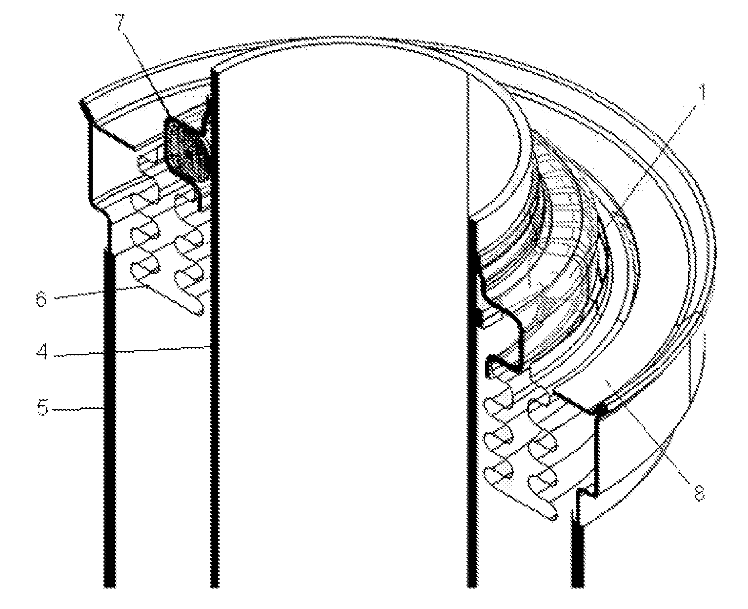
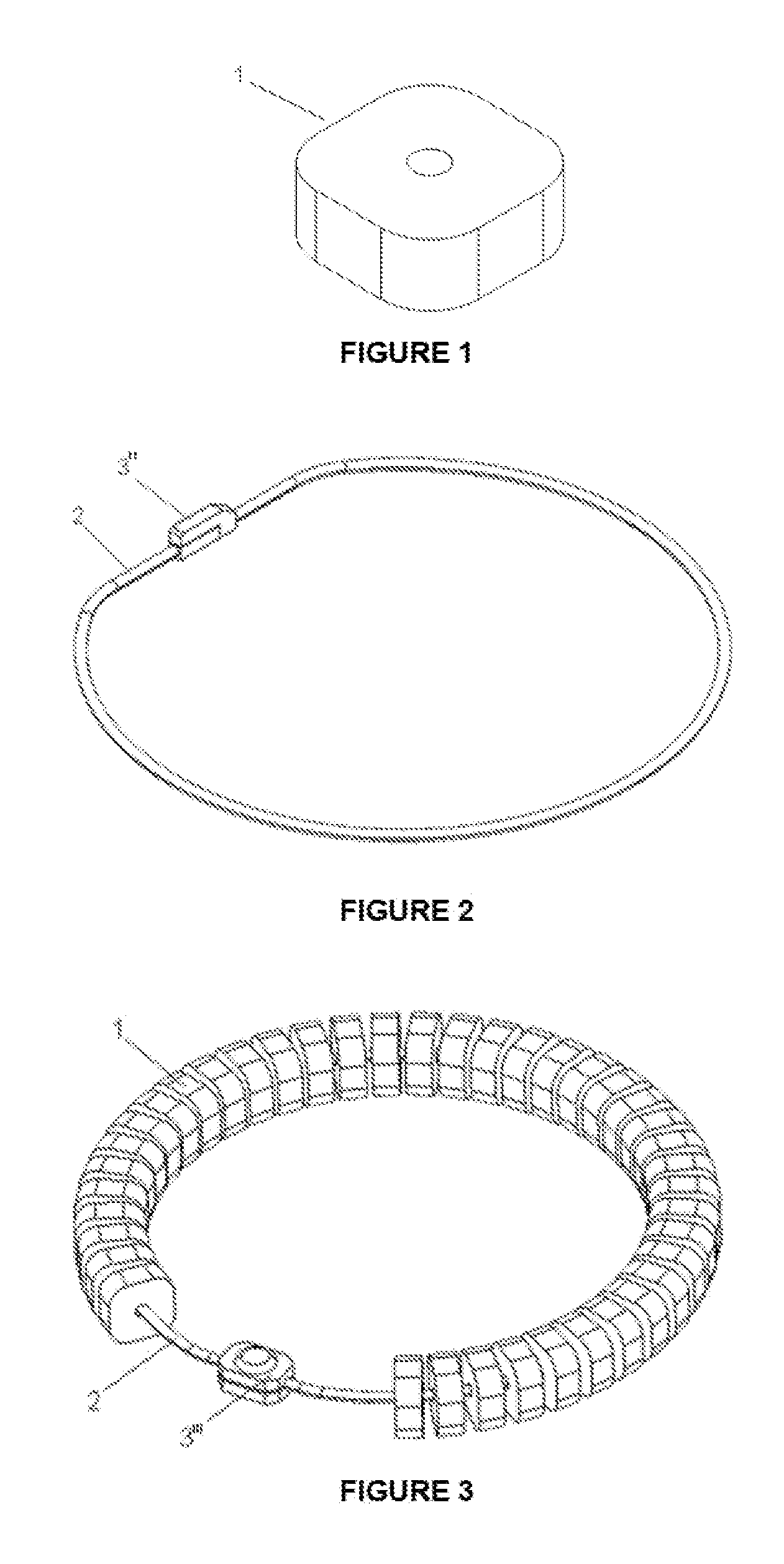
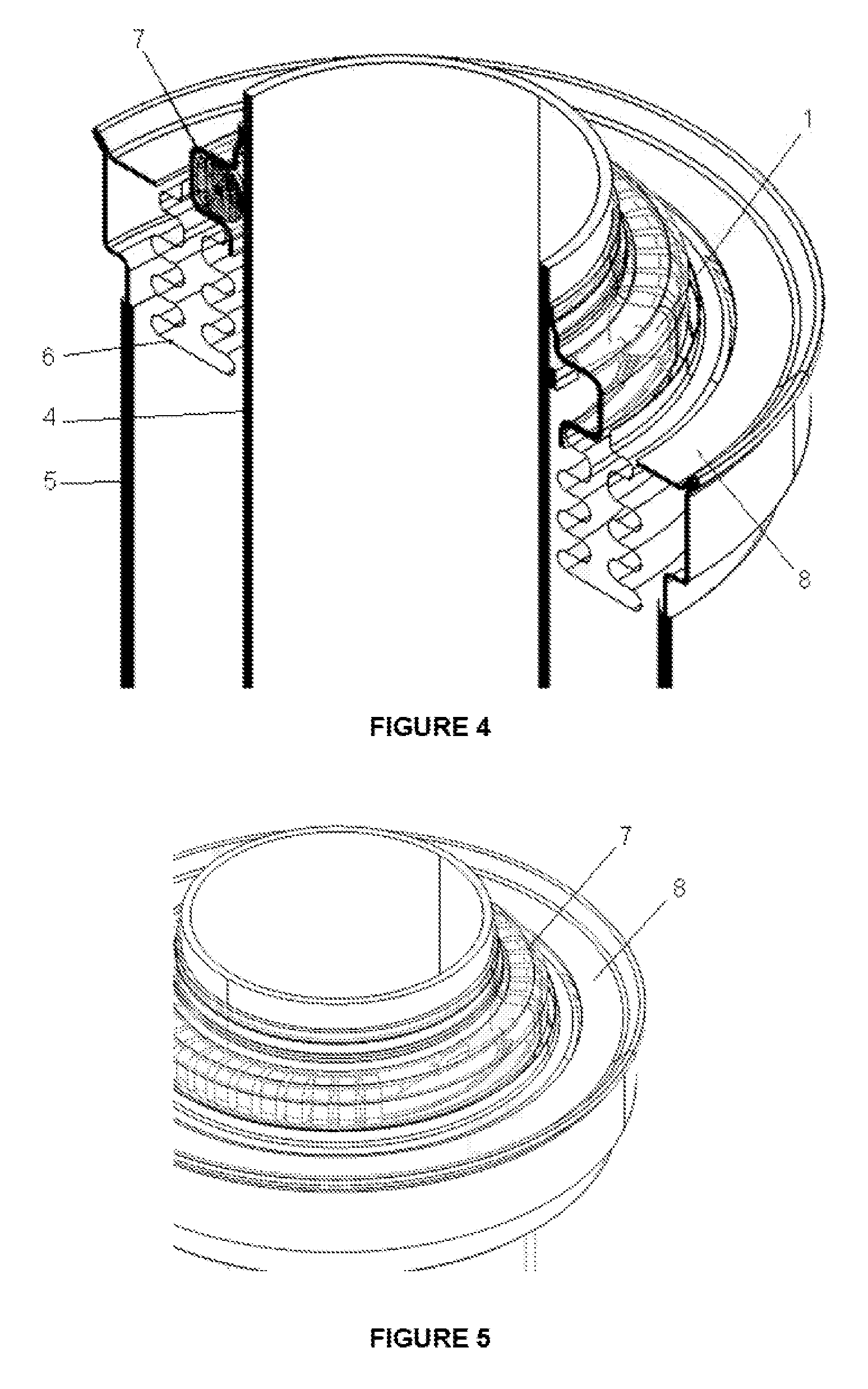
[0011]The invention consists of a non-evaporable getter system for the absorption of hydrogen that could occur in the vacuum area of a solar power absorber tube.
[0012]The function of the non-evaporable getter, despite its importance, should not interfere with the main purpose of the receptor tube which is to maximize its thermal performance. Its arrangement should allow this situation without compromising its role to ensure the correct aging of the product.
[0013]As mentioned above, its placement in the state of the art, originated a different housing geometry in one of the two ends in order to house it, which in-turn conditioned the value of the diameter of the glass or borosilicate cylinder.
[0014]To solve the problems found in the state of the art known, new design proposals linked to the geometry and arrangement of the non-evaporable getters assemblies have been developed.
[0015]Once the needs with regard to the amount of getter matter for tubes of 4 m in length and a plant half li...
PUM
 Abstract
Description
Claims
Application Information
 - R&D
- Intellectual Property
- Life Sciences
- Materials
- Tech Scout
- Unparalleled Data Quality
- Higher Quality Content
- 60% Fewer Hallucinations
Browse by: Latest US Patents, China's latest patents, Technical Efficacy Thesaurus, Application Domain, Technology Topic, Popular Technical Reports.
© 2025 PatSnap. All rights reserved.Legal|Privacy policy|Modern Slavery Act Transparency Statement|Sitemap|About US| Contact US: help@patsnap.com