
Water removing device for extremely high water content three-phase flow, and measurement device and method for extremely high water content three-phase flow

Active Publication Date: 2012-10-04
HAIMO TECH GRP CORP
View PDF9 Cites 28 Cited by
  • Summary
  • Abstract
  • Description
  • Claims
  • Application Information

AI Technical Summary

Benefits of technology

[0011]Therefore, in order to increase the measurement accuracy of the water and pure oil flow rate in the case of extremely high water cut, and meet the requirement for oilfield production metering, a first object of the present invention is to provide a water removing device mounted on the petroleum pipe line of the extremely high water cut oil-gas-water three-phase flow, so as to reduce the water cut of the oil-gas-water three-phase flow and meet the requirement of the measurement accuracy of the pure oil.
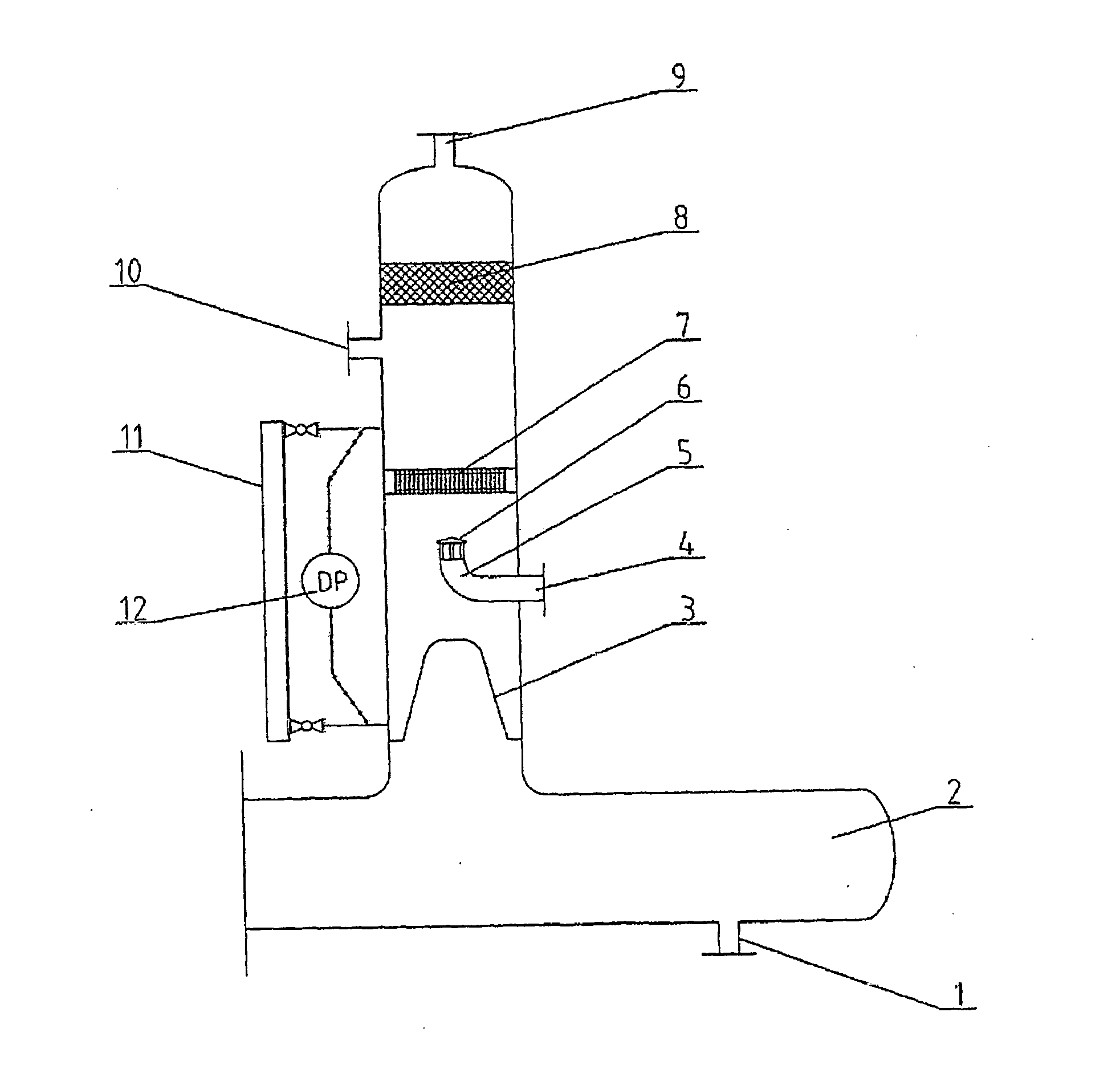
[0014]In order to achieve the first object, the invention is to provide a water removing device for extremely high water cut oil-gas-water three phase flow, which can automatically and effectively separate out most of the free water, reduce the water cut in the remaining oil-water mixture liquid, thus can measure the water cut under a lower water cut level, thereby increase the measurement accuracy for the flow rate of the pure oil. The water removing device of the present invention includes a housing, a liquid collection chamber, an inlet connection pipe section, a gas outlet connection pipe section and a free water outlet connection pipe section, a mixture liquid outlet connection pipe section, a mist eliminator, a fluid rectifier, an oil filter, an oil discharging duct with a baffle plate, and a pressure differential transmitter or other type of liquidometer, which is mounted on a side of the housing and used for liquid level control. A gas-liquid gravity separation process is occurred in the water removing device after the extremely high water cut oil-gas-water three phase flow entered into the water removing device via the inlet connection pipe section. The gas mist-eliminated via the mist eliminator is discharged from the gas outlet connection pipe section. The liquid entered into the lower portion of the water removing device via the liquid rectifier. The free water is discharged from the outlet of the free water outlet connection pipe section via the oil filter. The oil-water mixture or oil-gas-water mixture on the upper part of the liquid is discharged via the oil discharging duct. In the process of the free water removing, the pressure differential transmitter or the liquidometer may be used to detect the liquid level in the water removing device to provide an adjustment signal for the control system.
[0021]5) in the process of liquid discharging, the liquid level within the water removing device is real time detected by the pressure differential transmitter or the liquidometer; The control system of the device is used to adjust the opening degree of the control valve of the free water discharging pipe section and the control valve of the gas discharging pipe section according to the result of the liquid level in order to control the liquid level within the water removing device to a certain height thus to prevent any oil from entering the free water discharging pipe section, prevent the gas from entering the water discharging pipe section, or prevent the excessive gas from entering the oil discharging pipe section or prevent the liquid from entering the gas discharging pipe section.

Problems solved by technology

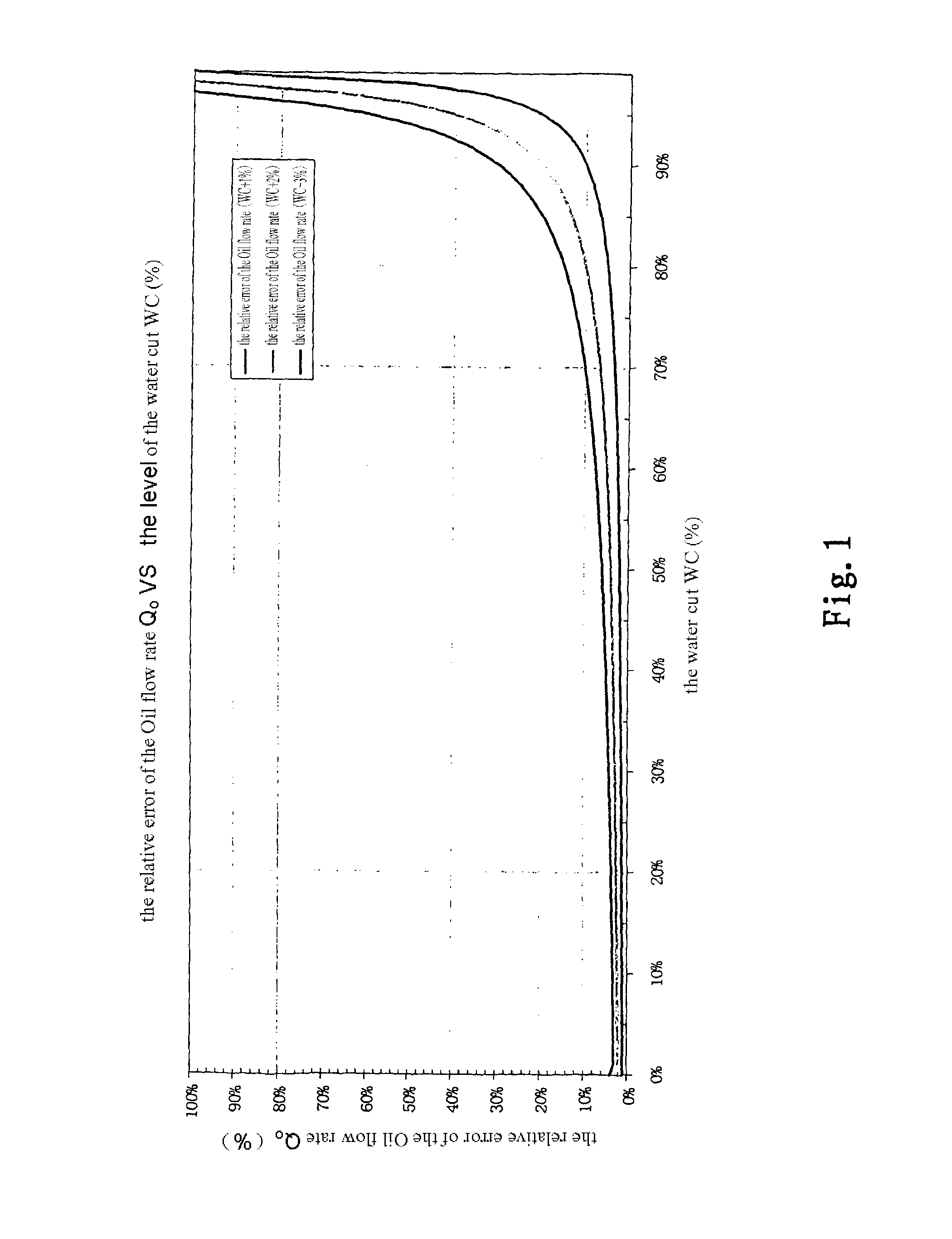
Therefore, at the level of the extremely high water cut, the measurement error of the water cut would cause a extremely great error of the pure oil measurement, which restrict in a great extent the application of the present multi-phase flow meter in this situation.
However, the costs of buying and operating the system is too high; a continuous real time metering could not be realized for a single well; the separation efficiency is affected by many factors; and particularly in the case of extremely high water cut, the system requires a longer stable time before metering, and the efficiency of oil-water separation is poor in the oil line, thereby the representation of the metering result of the pure oil is poor and error is great.
Secondly, since the structure and the flow process of the oil-gas-water three-phase separator are complex, and the separator is heavy and has a big footprint, thereby the maintenance and management of the separator are quite complex, so that the costs of establishment, operation and maintenance of the separator are high, which is detrimental to the automation of the production process and the management, especially in the marginal oilfields (particularly the oil fields in the stage of extremely high water cut).

Method used


Image

  • Water removing device for extremely high water content three-phase flow, and measurement device and method for extremely high water content three-phase flow
  • Water removing device for extremely high water content three-phase flow, and measurement device and method for extremely high water content three-phase flow
  • Water removing device for extremely high water content three-phase flow, and measurement device and method for extremely high water content three-phase flow

Examples


Embodiment Construction

[0036]Hereinafter, the embodiments of the invention are described in detail with reference to the drawings.

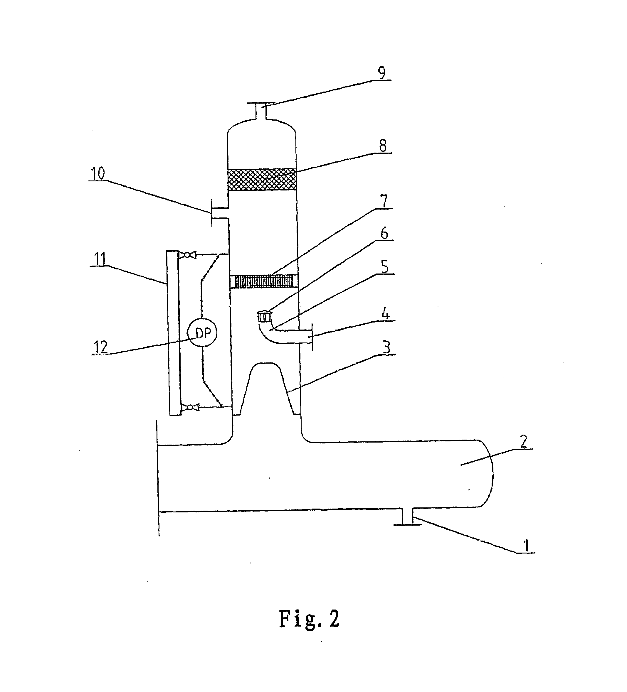
[0037]FIG. 2 is a schematic diagram of an embodiment of a water removing device for extremely high water cut oil-gas-water three phase flow of the invention.

[0038]In FIG. 2, a reference number 1 represents a free water outlet connection pipe section, a reference number 2 represents a liquid collection chamber, a reference number 3 represents an oil filter, a reference number 4 represents a mixture liquid outlet connection pipe section, a reference number 5 represents a fluid directing duct, a reference number 6 represents a baffle plate, a reference number 7 represents a fluid rectifier, a reference number 8 represents a mist eliminator, a reference number 9 represents a gas outlet connection pipe section, a reference number 10 represents an inlet connection pipe section, a reference number 11 represents a liquidometer, and a reference number 12 represents a pressure differenti...


PUM

PropertyMeasurementUnit
Timeaaaaaaaaaa
Flow rateaaaaaaaaaa
Volume ratioaaaaaaaaaa

Abstract

An extremely high water cut oil-gas-water three phase flow water removing device, which includes a mist eliminator (8), a fluid rectifier (7), a liquid collection chamber (2), a fluid directing duct (5), an inlet connection pipe section (10), a gas outlet connection pipe section (9), a mixture liquid exit connection pipe section (4), a free water outlet connection pipe section (1). Its function is to effectively remove most of the free water from the high water cut oil-air-water three phase flow mixture liquid. An extremely high water cut oil-air-water three phase flow measurement apparatus and a measurement method using the water removing device are also disclosed.

Description

FIELD OF THE INVENTION[0001]The invention relates to a water removing device for oil-gas-water three phase flow mounted to a petroleum pipe line of the oilfield, and a measurement apparatus which uses the water removing device and a method for measuring the flow rates of oil, gas and water in the three phase flow in the petroleum pipe line.DESCRIPTION OF THE PRIOR ART[0002]At present, many onshore oilfields have entered into a stage of extremely high water cut. The accurate flow rates of oil, gas and water in each of the extremely high water cut wells are the foundation of oil recovery, and they also are the main basis for production optimization and reservoir management.[0003]In order to obtain mentioned-above data, a multi-phase flow metering system has developed recently. The multi-phase flow metering system has been wildly applied to single-well metering due to the benefits such as its small footprint, simple installation and maintenance, high precision, and continuously real ti...

Claims


Application Information

Patent Timeline
IPC IPC(8): B01D17/02G01F1/34G06F19/00B01D19/00
CPCB01D17/0214B01D17/10B01D17/12B01D17/0208G01F1/34G01F1/74B01D19/0031
Inventor CHEN, JIGEWANG, ZHENGANGYU, HAIYE, JUNJIE
Owner HAIMO TECH GRP CORP
Learn More